helen@hbxinnuorollforming.com
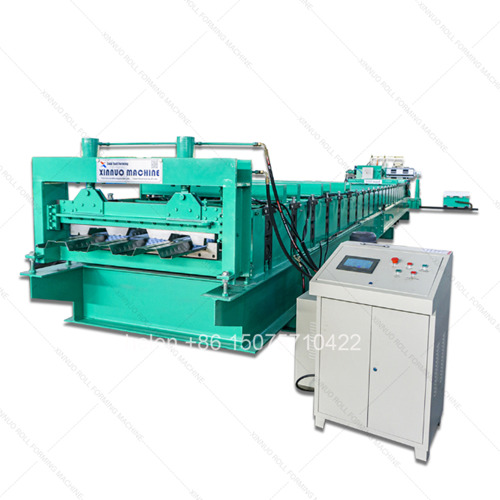
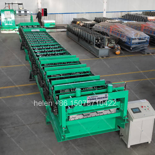
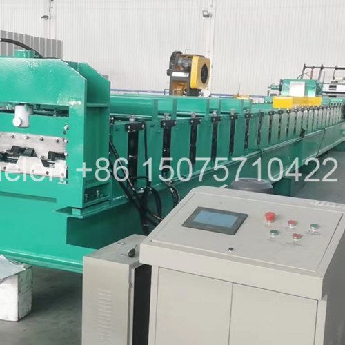
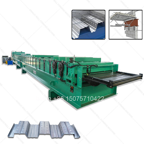
- Floor deck ribs run 50 to 153 mm deep, far beyond roof panel range
- Peak height, not coverage width, sets the forming row count
- Material at 0.8 to 1.5 mm drives frame, shaft, and motor selection
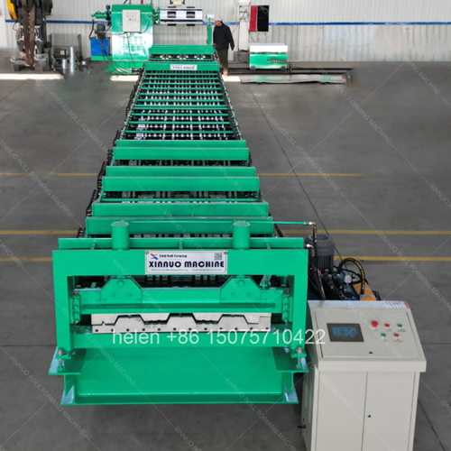
- Dual motors deliver balanced torque along a 14.5 m forming unit
- Closed deck adds re-entrant forming and a substantially longer roll train
- Specification matching should start from the structural requirement
- Under-rowed machines cause pooling, scratching, and twisted panels
A floor deck is not a roof panel with deeper ribs. It is a structural element that carries wet concrete during construction and then acts as tensile reinforcement once the slab has cured. That structural role is what makes the profile geometry demanding: ribs of 50 to 153 mm, material from 0.8 to 1.5 mm, and embossments pressed into the rib faces to grip the concrete. The consequence for the machine is that configuration cannot be chosen on coverage width alone.
This page sets out how a floor deck roll forming machine should be specified against the profile it has to produce. It covers why peak height rather than effective width governs the forming row count, how open and closed deck profiles change the machine fundamentally, how material thickness drives frame, shaft, chain, and motor selection, what the established profile families require in rows and feed width, when a switchable machine is the better commercial answer than two machines, and what information a buyer needs to supply for an accurate configuration and quotation.
| Profile Attribute | Effect on Machine Design | What It Determines |
|---|---|---|
| Peak height | The dominant factor. Each pass can only form a limited proportion of the total rib depth before the material tears or the friction becomes unmanageable. | The number of forming rows, the diameter of the rear wheels, and whether bearing-mounted wheels and pressure reinforcement are required |
| Effective coverage width | Sets the working width of the rollers and the feed width of the coil. | Roller length, shaft length, and coil specification — but not the number of passes |
| Rib count and pitch | Determines how the forming load is distributed across the roll face. | Roller profile tooling and the balance of forming pressure across the sheet width |
| Material thickness | Thicker steel requires more force per pass and greater rigidity throughout. | Frame grade, mid-plate thickness, shaft diameter, chain size, and motor rating |
| Open or closed geometry | Closed sections require the material to be formed back on itself into a re-entrant shape. | Additional forming rows, a dedicated locking roller set, and a longer forming unit |
| Embossment requirement | Dimple wheels are larger in diameter than neighbouring forming wheels. | Whether an anti-pooling clutch arrangement is required at the embossing row |
| Cut edge requirement | Affects the shear arrangement rather than the forming train. | Whether a three-blade or two-blade shear is specified, and the associated trim waste |
| Aspect | Open Deck | Closed Deck |
|---|---|---|
| Section shape | Trapezoidal ribs open at the top | Re-entrant or dovetail ribs, narrower at the top than at the base |
| Composite action | Relies on embossments and friction between concrete and rib face | Concrete wraps around the rib ends, creating mechanical interlock in addition to embossment grip |
| Typical application | General commercial and industrial floors, the majority of global demand | Long spans, elevated parking structures, floors where shear stud quantities must be minimised |
| Forming rows | 20 to 28 rows for the standard families | Up to 36 rows, since the section must be formed over and back into the re-entrant shape |
| Roller set | Conventional forming rolls plus an embossing row | Additional dedicated locking roller set for the re-entrant return |
| Representative profile | 750, 1000, 688, 1025, 915, 720, 780, 870, 990 families | 820 class re-entrant profile with a 1220 mm feed width |
| Machine length and cost | Standard forming unit length | Longer roll train, heavier drive requirement, and a materially higher machine price |
Each forming pass makes an incremental shape change. The deeper the final rib, the more passes are required, and the relationship is not linear — deep ribs also require progressively larger rear wheels and additional support of the roll train. A machine with fewer rows than the profile requires produces pooling, surface scratching, and panels that come out twisted or wavy on thick material.
| Peak Height | Rows Required | Configuration Notes |
|---|---|---|
| 39 – 51 mm | 18 – 22 rows | The lightest floor deck class. Still deeper than any roof panel profile, but achievable on an economy configuration with a 400H frame and a 90 mm shaft. |
| 50 – 76 mm | 22 – 27 rows | The standard industrial range covering the 750, 1000, 720, 780 and 688 families. Bearing-mounted rear wheels and pressure reinforcement are required at this depth. |
| 76 – 100 mm | 27 – 30 rows | Heavy class. Higher motor rating and a heavier chain are needed to maintain feed force through the longer train. |
| 100 – 153 mm | 30 – 36 rows | Extreme class represented by 868 and the deepest 915 variants. Widest feed width, heaviest shaft, and the largest motor configuration available. |
| Maximum Thickness | Frame | Shaft | Motor Configuration | Chain | Application Character |
|---|---|---|---|---|---|
| Up to 0.9 mm | 400H | Φ90 mm | 2 × 11 kW | 2 inch | Light commercial flooring, entry configuration |
| Up to 1.2 mm | 450H | Φ95 mm | 2 × 11 kW | 2 inch external | The standard industrial specification |
| Up to 1.5 mm | 450H | Φ95 mm | 2 × 15 kW | 2 inch external | Heavy structural decking, long-span applications |
| Above 1.5 mm | 450H heavy duty | Φ105 – 115 mm | 2 × 22 kW | 2.5 inch | Specialist heavy sections and extreme profiles |
Dual motors are not a marketing specification on this product. A single motor cannot deliver balanced torque across a forming train of 14.5 metres, and the result on thick, deep-ribbed material is uneven forming pressure that leaves panels twisted or wavy. The twin drive provides torque at both ends of the train so the load is shared rather than concentrated.
| Profile Class | Effective Width | Ribs | Rib Height | Feed Width | Rows Required | Character |
|---|---|---|---|---|---|---|
| 750 class | 750 mm | 3 | 51 mm | 1000 mm | 20 – 24 | Highest order frequency; the benchmark industrial deck |
| 1000 class | 1000 mm | 3 | 50 mm | 1220 mm | 24 | Wide coverage, efficient on large floor plates |
| 688 class | 688 mm | 2 | 76 mm | 1000 mm | 24 – 27 | Deep two-rib section, structural emphasis |
| 1025 class | 1025 mm | 3 | 51 mm | 1250 mm | 24 – 28 | Widest coverage in the standard range |
| 720 class | 720 mm | 3 | 53 mm | 1000 mm | 22 – 24 | Close relative of the 750 class, often interchangeable |
| 915 class | 915 mm | 3 | 76 mm | 1250 mm | 26 – 28 | Deep rib with wide coverage, heavier drive requirement |
| 780 class | 780 mm | 3 | 50 mm | 1000 mm | 20 – 24 | Companion profile to the 750 class |
| 760 class | 760 mm | 3 | 51 mm | 1000 mm | 22 | Regional variant of the standard 3-rib deck |
| 870 class | 870 mm | 3 | 60 mm | 1250 mm | 24 | Mid-depth, wide coverage |
| 990 class | 990 mm | 3 | 50 mm | 1219 mm | 24 | Metrically dimensioned wide deck |
| 820 closed | 820 mm | 3 re-entrant | 50 mm | 1220 mm | 36 | Closed deck, highest row count in the range |
| 868 deep | 833 mm | 3 | 153 mm | 1500 mm | 34 | Deepest profile class, heaviest configuration |
| Option | When It Is the Right Answer |
|---|---|
| Switchable profile machine | Where two closely related deck widths are both required — commonly 750 and 780, 720 and 750, 914 and 944, or 915 and 950. A profile change kit allows one machine to serve both, which costs more than a single-profile machine but considerably less than two. |
| Computer-controlled automatic adjustment | For high-volume production where changeover time and operator skill are significant cost factors. Reduces the skill requirement and shortens the change, at a higher machine price. |
| Archway frame construction with hydraulic motor drive | The premium tier, for high-specification projects and developed markets where smoothness of operation and long-term stability justify the higher cost. |
| Built-in or external reducer mounting | Built-in gives a more compact machine; external is easier to service. Built-in has become the more common choice on recent designs. |
| Three-blade or two-blade shear | Three-blade produces a cleaner edge with perfect profile at the cost of roughly 10 mm of trim waste per cut, which must be cleared promptly or it will damage the blade. Two-blade produces no waste with negligible edge deformation that does not affect structural performance. |
| Tier | Configuration | Suited To |
|---|---|---|
| Economy | 18 – 20 rows, 400H frame, Φ90 mm shaft, 2 × 11 kW | Shallowest deck profiles and lightest material, where order volumes are modest |
| Standard | 22 – 24 rows, 450H frame, Φ95 mm shaft, 2 × 11 kW | The benchmark industrial configuration covering the mainstream deck families |
| Heavy | 26 – 28 rows, 450H frame, Φ95 mm shaft, 2 × 15 kW | Deep-rib and wide-coverage profiles, material up to 1.5 mm |
| Premium | 30 – 36 rows, 450H frame, Φ95 – 105 mm shaft, 2 × 15 – 22 kW | Extreme profiles, closed deck, and the largest structural sections |
| Flagship | 32 rows, archway frame, hydraulic motor with gearbox | High-specification projects requiring the highest stability and smoothest operation |
| Information | Why It Changes the Answer |
|---|---|
| Profile drawing or section detail | The definitive input. Coverage width, rib count, rib height, and rib shape all read directly from the drawing and determine rows, rollers, and feed width. |
| Effective width and rib height | Where no drawing is available, these two figures together are enough to identify the profile family and the corresponding row requirement. |
| Open or closed section | Determines whether the standard roll train applies or whether the re-entrant forming rows and locking roller set are required. |
| Material grade and thickness range | Sets the frame grade, shaft diameter, chain size, and motor rating. Galvanized, aluminium-zinc coated, and pre-painted stock behave differently in forming. |
| Coil width and coil weight | Determines the decoiler specification and the feed width that the entry guide must accommodate. |
| Required sheet lengths and range | Affects the run-out arrangement and the cut length programming, and informs whether a floor-standing shear is appropriate. |
| Required output rate | Determines whether the standard configuration is sufficient or whether a higher-speed or automatic adjustment machine is justified. |
| One profile or two | Decides between a single-profile machine and a switchable configuration, which is a significant cost and footprint decision. |
| Destination market standard | Section dimensions, coating specifications, and documentation requirements differ by market, and the profile may need to match a local standard designation. |
| Sheet count and stacking requirement | Determines whether a floor-level shear with gravity discharge and a manual or powered stacking arrangement is adequate. |
| Parameter | Standard Range |
|---|---|
| Profile type | Open trapezoidal deck and closed re-entrant deck, produced to the buyer's profile drawing or a matched standard section |
| Effective coverage width | 688 – 1025 mm across the standard families; wider by drawing specification |
| Rib height | 39 – 153 mm depending on profile class |
| Forming rows | 18 – 36 rows, selected against rib height, section type, and material thickness |
| Frame | 400H – 450H welded H-section with 10 mm flange thickness and a 18 – 25 mm mid plate |
| Shaft | Φ90 – 115 mm round bar, rough turned then precision ground, improving straightness and surface finish |
| Forming wheels | 45# steel, forged, then rough turned, quenched to HRC 45 – 50, finish turned, keyed, polished, and chrome plated |
| Embossment row | Dedicated dimple wheel row with a clutch arrangement that disengages drive once material has passed, allowing the wheels to be carried by downstream rollers |
| Rear forming rows | Bearing-mounted oversized wheels on approximately the rear ten rows, converting the action from pulling to pushing |
| Pressure reinforcement | Reinforcement bars fitted at the embossment, main drive, rib forming, and sizing rows to increase effective shaft rigidity |
| Gear drives | Fitted at the embossment row, ahead of the bearing wheel section, and at the exit rows to increase feed and pulling force |
| Transmission | 2 inch external roller chain as standard, 2.5 inch for the heaviest profiles, with hardened sprockets |
| Motor configuration | 2 × 11 kW standard, 2 × 15 kW for heavy profiles, 2 × 22 kW above 1.5 mm material |
| Shear | Dual-cylinder floor-level shear with balanced cutting force, positioned so finished panels discharge to the stacking area |
| Blade options | Three-blade for the cleanest edge with approximately 10 mm trim waste, or two-blade for zero waste with negligible edge deformation |
| Material capability | 0.8 – 1.5 mm standard; galvanized, aluminium-zinc coated, and pre-painted coil |
| Forming speed | 8 – 18 m/min depending on profile depth and material thickness |
| Cut length tolerance | ±1.5 mm |
| Control system | PLC with colour touchscreen HMI and stored recipe banks for the profile produced |
| Line length | Approximately 22 m overall, with a forming unit width of about 2.75 m and about 6.5 m at the decoiler side |
| Electrical supply | 380 V / 50 Hz / 3-phase standard; alternative voltages and frequencies by destination |
| Certification | CE marking and ISO 9001:2015 compliant manufacturing |
Coil loading on the decoiler, strip entry through the guide, progressive forming across the roll train with embossment at the dimple row, sizing over the final passes, length measurement, dual-cylinder cutting at floor level, and discharge to the stacking position follow the established sequence, with the panel geometry set by the roller profile rather than by operator adjustment.
Hebei Xinnuo is a professional cold roll forming machinery manufacturer with 20+ years of experience. We specialize in C/Z purlin machines, roof panel roll formers, floor deck machines, and custom profile solutions — exported to 50+ countries worldwide.