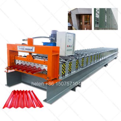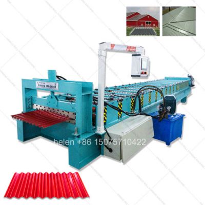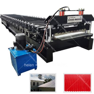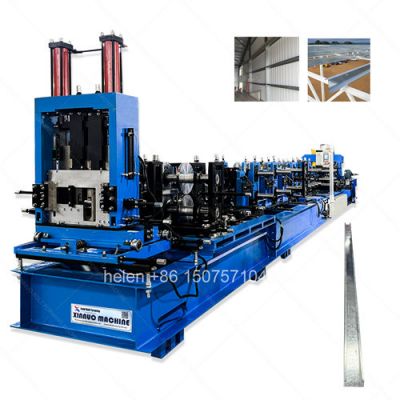
helen@hbxinnuorollforming.com
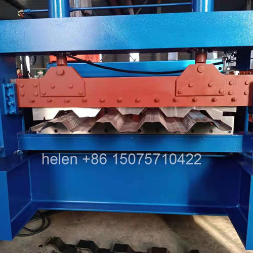
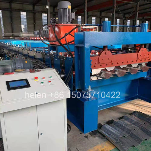
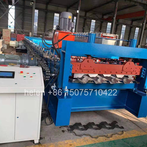
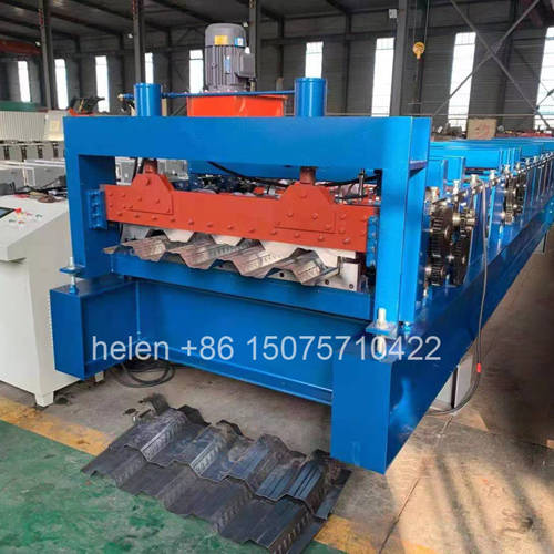
The forming train draws most of the attention when a metal deck roll forming machine is specified, but the coil and the equipment that feeds it set the practical limits on the whole line. A deck profile is formed from a coil considerably wider than the finished cover width, the coil is heavy enough to require mechanical handling, and the condition of the strip as it enters the first pass determines what happens in every pass after it. A machine with an excellent roll train and a poorly specified decoiler will underperform a more modest machine with a front end matched to the material it actually receives.
This page covers the coil and front-end side of a metal deck roll forming machine: how feed width is established from the profile rather than from the frame, which coil parameters genuinely change the machine specification, what decoiler configurations are available and how to choose between them, how coil is loaded and what that means for changeover time and labour, what strip defects originate in the coil rather than the machine and how they present, and which practices at the entry end protect the output the forming unit is capable of delivering.
Cover width is what the customer buys; feed width is what the machine consumes. The difference is the material absorbed by the ribs, the side laps, and any edge trim. Establishing feed width correctly is the first specification step, because everything upstream — coil ordering, decoiler working width, entry guide range, and the guides in the first forming passes — follows from it.
Profile Class
Cover Width
Rib Height
Required Feed Width
Implication for Coil Supply
750 class750 mm51 mm1000 mmThe most commonly available coil width, which is a practical advantage in procurement and in lead time
1000 class1000 mm50 mm1220 mmA standard coil width, widely stocked in most markets
688 class688 mm76 mm1000 mmNarrow cover from standard width coil; a high proportion of the coil becomes rib material rather than cover
1025 class1025 mm51 mm1250 mmRequires a wider coil stock specifically for this profile, which affects sourcing flexibility
720 class720 mm53 mm1000 mmShares coil width with the 750 class, allowing both to run from one coil stock
915 class915 mm76 mm1250 mmWide coil and deep rib together, so the forming load and the coil handling requirement are both high
780 class780 mm50 mm1000 mmStandard coil width, convenient when run alongside the 750 class
760 class760 mm51 mm1000 mmStandard coil width
870 class870 mm60 mm1250 mmWider coil than the cover width alone would suggest
990 class990 mm50 mm1219 mmMetrically dimensioned coil requirement, which may be less widely stocked than 1220 mm
820 closed820 mm50 mm re-entrant1220 mmThe re-entrant shape consumes substantially more material relative to cover width than an open profile
868 deep833 mm153 mm1500 mmThe widest coil in the range and the heaviest handling requirement at the entry end
Parameter
Why It Matters on a Deck Line
What It Determines
Coil width
Must match the feed width for the profile being produced, with a small tolerance for guiding
Decoiler working width, entry guide range, and the guides within the first forming passes
Material thickness
Deck coil runs at 0.8 to 1.5 mm, and thickness is the primary driver of forming load
Frame grade, shaft diameter, chain size, motor rating, and the configuration tier of the machine
Coil weight
Deck coil is heavy enough that it cannot be handled manually at any stage of loading
Mandrel and decoiler load capacity, and the lifting equipment required at the machine position
Coil inner diameter
The mandrel must expand to grip the inner wrap positively, without slipping under forming tension
Mandrel expansion range and the decoiler specification
Coil outer diameter
Determines the physical envelope the decoiler must accommodate and the clearance available around it
Decoiler dimensions, position, and the space required at the entry end of the line
Coating type
Pre-painted and aluminium-zinc coated stock mark more readily and behave differently in forming
Guide material and finish, and the handling provisions along the whole line
Coil hardness and grade
Higher-strength deck steel requires more forming force and springs back more after each pass
Forming row count and the pressure provision through the training
Coil edge condition
A damaged or burred coil edge tracks poorly and marks the guides as it passes
Entry guide design and the practical tolerance the line can accept on incoming coil
Coil camber and flatness
Strip that is not straight will not track straight, regardless of guide adjustment
Whether a straightener or levelling provision is required ahead of the forming unit
Configuration
Character
Suited To and Consideration
A-frame decoiler
A compact, heavily built frame carrying the mandrel, occupying a relatively small floor footprint at the entry end
Standard provision on deck lines. Approximately 1,450 mm in width and 6,500 mm in height on a typical 22 m line, so the decoiler itself is a substantial structure rather than an accessory.
Manual mandrel expansion
The mandrel is expanded and contracted by hand to grip or release the coil
Lower cost and fewer components to fail, but every coil change involves physical effort at the mandrel and slows the change. Workable where changes are infrequent.
Hydraulic mandrel expansion
The mandrel is expanded and contracted hydraulically from the control position
Faster and more consistent coil changes, with the grip force set and repeatable. Justified where the line runs multiple coil changes per shift.
With coil car
A powered carriage that lifts and presents the coil to the mandrel at the correct height and alignment
Removes the most difficult part of coil loading. Where coil is heavy and changes are frequent, this is the provision that most directly reduces changeover time.
Without coil car
Coil is presented by crane or forklift and loaded directly onto the mandrel
Viable where a crane is available and positioned to present the coil squarely. Requires more skill and time per change than a coil car.
Coil staging provision
Racked or floor position adjacent to the decoiler holding the next coils
Not part of the machine as supplied, but decisive for actual changeover time. Coil stored across the workshop adds a retrieval task to every change.
Method
Requirement at the Site
Effect on Changeover and Output
Overhead crane
A crane of adequate capacity with clear access directly above the decoiler
The fastest manual method when the crane is available and not committed elsewhere. Where the crane serves several machines, waiting time becomes part of the changeover.
Forklift
Adequate clear floor space on the loading side and a route that does not cross production areas
Practical where crane access is not available, but positioning a heavy coil accurately on a mandrel with a forklift takes longer and is less precise.
Coil car
Coil placed on the car by crane or forklift, with the car then doing the final positioning
Separates the lifting task from the positioning task. The crane only has to deliver coil to the car, which shortens the time the crane is occupied and the time the machine is stopped.
Coil staged at the machine
Space for two or three coils immediately adjacent to the decoiler
Removes retrieval and transport from the changeover entirely. This is usually the cheapest improvement available to a line that changes coil frequently.
Coil retrieved from store each time
Storage elsewhere in the building or yard
Every change begins with a retrieval task that machine design cannot compensate for. Coil transport becomes a larger component of downtime than the change itself.
Defect
Origin
How It Presents and What It Costs
CamberCoil supplied with a lateral curve from the rolling mill or from slittingStrip will not run straight regardless of guide setting. Produces panels with unequal side laps and load concentrated on one side of the forming train.
Edge damageHandling before delivery, or poor storage and strapping practiceBurred or distorted edges mark the entry guides and can initiate a tracking fault at the first pass.
Coil set or crossbowThe natural tendency of coiled steel to remain curved when unrolledStrip enters the first pass with residual curvature, which the forming train must then correct rather than simply shape.
Thickness variationRolling tolerance within the coil or between coilsForming load varies through the run. Material at the top of the tolerance range can push a machine configured at its limit into jamming.
Tight or slack inner wrapCoil winding condition at the millA tight inner wrap resists mandrel expansion and can slip under forming tension; a slack wrap causes uneven pay-off.
Surface contaminationOil, moisture, or storage debris on the coil surfaceTransfers to the rolls and then to subsequent panels. On coated stock the marking is permanent and the whole run is at risk.
Coating damage within the coilInter-wrap abrasion during transportAppears as intermittent marks that cannot be attributed to any wheel position, because the cause occurred before the machine saw the material.
Corrosion between wrapsMoisture ingress during storage or shippingStaining that shows through forming and is only discovered on the finished panel or after installation.
Practice
Effect on the Line
Confirm coil specification against the order before loadingSeconds of checking prevent a run produced from the wrong gauge or coating, which is the most expensive form of scrap on a deck line because it is discovered after full forming.
Inspect incoming coil on receipt, not at the machineEdge damage, camber, and inter-wrap corrosion are supplier or logistics issues. Identified on receipt, they can be raised with the supplier; found at the machine, they become a production stoppage.
Stage the next coil before the current run endsRemoves the retrieval step from the changeover and allows the loading task to run in parallel with production rather than after it.
Maintain the mandrel mechanismA stiff or poorly lubricated mandrel adds time to every single coil change and grips inconsistently, which presents as a forming fault.
Keep the entry guide clean and free of coating build-upBuild-up on the guides marks the strip edge and progressively shifts the tracking position through the run.
Decide the coil tail procedure in advanceWhether the tail is threaded through to completion or scrapped is a decision that should not be made mid-change, and making it in advance removes both time and scrap from the operation.
Record coil source against quality outcomesA recurring surface or thickness problem traced to one supplier is a purchasing decision, not a machine adjustment. Without records the distinction is never made.
Match coil stock to the profiles actually producedProfiles that share a feed width can be run from one coil stock, which reduces both the variety of coil held and the number of coil changes required.
Parameter
Standard Range
Profile typeOpen trapezoidal deck and closed re-entrant deck, produced to the buyer's profile drawing or a matched standard section
Effective coverage width688 – 1025 mm across the standard families; wider by drawing specification
Feed width1000 – 1500 mm depending on profile class, established from the profile rather than the frame
Rib height39 – 153 mm depending on profile class
Forming rows18 – 36 rows, selected against rib height, section type, and material thickness
Frame400H – 450H welded H-section with 10 mm flange thickness and a 18 – 25 mm mid plate
ShaftΦ90 – 115 mm round bar, rough turned then precision ground
Forming wheels45# forged steel, quenched to HRC 45 – 50, finish turned, keyed, polished, and chrome plated
Transmission2 inch external roller chain standard, 2.5 inch for the heaviest profiles
Motor configuration2 × 11 kW standard, 2 × 15 kW heavy, 2 × 22 kW above 1.5 mm material
DecoilerA-frame construction of approximately 1,450 mm width and 6,500 mm height on a standard line
Mandrel expansionManual or hydraulic, specified against the number of coil changes per shift
Coil loading provisionCrane, forklift, or coil car, with coil car recommended where changes are frequent and coil is heavy
ShearDual-cylinder hydraulic shear at floor level for balanced force and gravity-assisted panel discharge
Material capability0.8 – 1.5 mm standard; galvanized, aluminium-zinc coated, and pre-painted coil at feed widths from 1000 to 1500 mm
Forming speed8 – 18 m/min depending on profile depth and material thickness
Cut length tolerance±1.5 mm
Control systemPLC with colour touchscreen HMI, sheet count control, and stored recipe banks
Line lengthApproximately 22 m overall, comprising a forming unit of about 14.5 m, a control section of about 3 m, and an output bracket of about 3 m
Forming unit widthApproximately 2,750 mm, with approximately 6,500 mm at the decoiler side
Electrical supply380 V / 50 Hz / 3-phase standard; alternative voltages and frequencies by destination
CertificationCE marking and ISO 9001:2015 compliant manufacturing
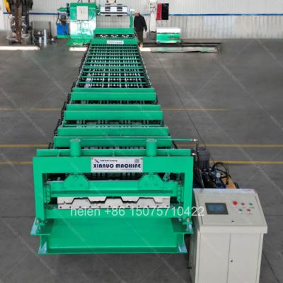
Coil loaded onto the decoiler mandrel, strip pay-off and entry through the guide, progressive forming across the roll train with embossment at the dimple row, sizing over the final passes, length measurement, dual-cylinder cutting at floor level, and gravity discharge to the stacking position follow the established sequence, with the coil specification and feed width established before forming begins.
The forming train draws most of the attention when a metal deck roll forming machine is specified, but the coil and the equipment that feeds it set the practical limits on the whole line. A deck profile is formed from a coil considerably wider than the finished cover width, the coil is heavy enough to require mechanical handling, and the condition of the strip as it enters the first pass determines what happens in every pass after it. A machine with an excellent roll train and a poorly specified decoiler will underperform a more modest machine with a front end matched to the material it actually receives.
This page covers the coil and front-end side of a metal deck roll forming machine: how feed width is established from the profile rather than from the frame, which coil parameters genuinely change the machine specification, what decoiler configurations are available and how to choose between them, how coil is loaded and what that means for changeover time and labour, what strip defects originate in the coil rather than the machine and how they present, and which practices at the entry end protect the output the forming unit is capable of delivering.
Cover width is what the customer buys; feed width is what the machine consumes. The difference is the material absorbed by the ribs, the side laps, and any edge trim. Establishing feed width correctly is the first specification step, because everything upstream — coil ordering, decoiler working width, entry guide range, and the guides in the first forming passes — follows from it.
| Profile Class | Cover Width | Rib Height | Required Feed Width | Implication for Coil Supply |
|---|---|---|---|---|
| 750 class | 750 mm | 51 mm | 1000 mm | The most commonly available coil width, which is a practical advantage in procurement and in lead time |
| 1000 class | 1000 mm | 50 mm | 1220 mm | A standard coil width, widely stocked in most markets |
| 688 class | 688 mm | 76 mm | 1000 mm | Narrow cover from standard width coil; a high proportion of the coil becomes rib material rather than cover |
| 1025 class | 1025 mm | 51 mm | 1250 mm | Requires a wider coil stock specifically for this profile, which affects sourcing flexibility |
| 720 class | 720 mm | 53 mm | 1000 mm | Shares coil width with the 750 class, allowing both to run from one coil stock |
| 915 class | 915 mm | 76 mm | 1250 mm | Wide coil and deep rib together, so the forming load and the coil handling requirement are both high |
| 780 class | 780 mm | 50 mm | 1000 mm | Standard coil width, convenient when run alongside the 750 class |
| 760 class | 760 mm | 51 mm | 1000 mm | Standard coil width |
| 870 class | 870 mm | 60 mm | 1250 mm | Wider coil than the cover width alone would suggest |
| 990 class | 990 mm | 50 mm | 1219 mm | Metrically dimensioned coil requirement, which may be less widely stocked than 1220 mm |
| 820 closed | 820 mm | 50 mm re-entrant | 1220 mm | The re-entrant shape consumes substantially more material relative to cover width than an open profile |
| 868 deep | 833 mm | 153 mm | 1500 mm | The widest coil in the range and the heaviest handling requirement at the entry end |
| Parameter | Why It Matters on a Deck Line | What It Determines |
|---|---|---|
| Coil width | Must match the feed width for the profile being produced, with a small tolerance for guiding | Decoiler working width, entry guide range, and the guides within the first forming passes |
| Material thickness | Deck coil runs at 0.8 to 1.5 mm, and thickness is the primary driver of forming load | Frame grade, shaft diameter, chain size, motor rating, and the configuration tier of the machine |
| Coil weight | Deck coil is heavy enough that it cannot be handled manually at any stage of loading | Mandrel and decoiler load capacity, and the lifting equipment required at the machine position |
| Coil inner diameter | The mandrel must expand to grip the inner wrap positively, without slipping under forming tension | Mandrel expansion range and the decoiler specification |
| Coil outer diameter | Determines the physical envelope the decoiler must accommodate and the clearance available around it | Decoiler dimensions, position, and the space required at the entry end of the line |
| Coating type | Pre-painted and aluminium-zinc coated stock mark more readily and behave differently in forming | Guide material and finish, and the handling provisions along the whole line |
| Coil hardness and grade | Higher-strength deck steel requires more forming force and springs back more after each pass | Forming row count and the pressure provision through the training |
| Coil edge condition | A damaged or burred coil edge tracks poorly and marks the guides as it passes | Entry guide design and the practical tolerance the line can accept on incoming coil |
| Coil camber and flatness | Strip that is not straight will not track straight, regardless of guide adjustment | Whether a straightener or levelling provision is required ahead of the forming unit |
| Configuration | Character | Suited To and Consideration |
|---|---|---|
| A-frame decoiler | A compact, heavily built frame carrying the mandrel, occupying a relatively small floor footprint at the entry end | Standard provision on deck lines. Approximately 1,450 mm in width and 6,500 mm in height on a typical 22 m line, so the decoiler itself is a substantial structure rather than an accessory. |
| Manual mandrel expansion | The mandrel is expanded and contracted by hand to grip or release the coil | Lower cost and fewer components to fail, but every coil change involves physical effort at the mandrel and slows the change. Workable where changes are infrequent. |
| Hydraulic mandrel expansion | The mandrel is expanded and contracted hydraulically from the control position | Faster and more consistent coil changes, with the grip force set and repeatable. Justified where the line runs multiple coil changes per shift. |
| With coil car | A powered carriage that lifts and presents the coil to the mandrel at the correct height and alignment | Removes the most difficult part of coil loading. Where coil is heavy and changes are frequent, this is the provision that most directly reduces changeover time. |
| Without coil car | Coil is presented by crane or forklift and loaded directly onto the mandrel | Viable where a crane is available and positioned to present the coil squarely. Requires more skill and time per change than a coil car. |
| Coil staging provision | Racked or floor position adjacent to the decoiler holding the next coils | Not part of the machine as supplied, but decisive for actual changeover time. Coil stored across the workshop adds a retrieval task to every change. |
| Method | Requirement at the Site | Effect on Changeover and Output |
|---|---|---|
| Overhead crane | A crane of adequate capacity with clear access directly above the decoiler | The fastest manual method when the crane is available and not committed elsewhere. Where the crane serves several machines, waiting time becomes part of the changeover. |
| Forklift | Adequate clear floor space on the loading side and a route that does not cross production areas | Practical where crane access is not available, but positioning a heavy coil accurately on a mandrel with a forklift takes longer and is less precise. |
| Coil car | Coil placed on the car by crane or forklift, with the car then doing the final positioning | Separates the lifting task from the positioning task. The crane only has to deliver coil to the car, which shortens the time the crane is occupied and the time the machine is stopped. |
| Coil staged at the machine | Space for two or three coils immediately adjacent to the decoiler | Removes retrieval and transport from the changeover entirely. This is usually the cheapest improvement available to a line that changes coil frequently. |
| Coil retrieved from store each time | Storage elsewhere in the building or yard | Every change begins with a retrieval task that machine design cannot compensate for. Coil transport becomes a larger component of downtime than the change itself. |
| Defect | Origin | How It Presents and What It Costs |
|---|---|---|
| Camber | Coil supplied with a lateral curve from the rolling mill or from slitting | Strip will not run straight regardless of guide setting. Produces panels with unequal side laps and load concentrated on one side of the forming train. |
| Edge damage | Handling before delivery, or poor storage and strapping practice | Burred or distorted edges mark the entry guides and can initiate a tracking fault at the first pass. |
| Coil set or crossbow | The natural tendency of coiled steel to remain curved when unrolled | Strip enters the first pass with residual curvature, which the forming train must then correct rather than simply shape. |
| Thickness variation | Rolling tolerance within the coil or between coils | Forming load varies through the run. Material at the top of the tolerance range can push a machine configured at its limit into jamming. |
| Tight or slack inner wrap | Coil winding condition at the mill | A tight inner wrap resists mandrel expansion and can slip under forming tension; a slack wrap causes uneven pay-off. |
| Surface contamination | Oil, moisture, or storage debris on the coil surface | Transfers to the rolls and then to subsequent panels. On coated stock the marking is permanent and the whole run is at risk. |
| Coating damage within the coil | Inter-wrap abrasion during transport | Appears as intermittent marks that cannot be attributed to any wheel position, because the cause occurred before the machine saw the material. |
| Corrosion between wraps | Moisture ingress during storage or shipping | Staining that shows through forming and is only discovered on the finished panel or after installation. |
| Practice | Effect on the Line |
|---|---|
| Confirm coil specification against the order before loading | Seconds of checking prevent a run produced from the wrong gauge or coating, which is the most expensive form of scrap on a deck line because it is discovered after full forming. |
| Inspect incoming coil on receipt, not at the machine | Edge damage, camber, and inter-wrap corrosion are supplier or logistics issues. Identified on receipt, they can be raised with the supplier; found at the machine, they become a production stoppage. |
| Stage the next coil before the current run ends | Removes the retrieval step from the changeover and allows the loading task to run in parallel with production rather than after it. |
| Maintain the mandrel mechanism | A stiff or poorly lubricated mandrel adds time to every single coil change and grips inconsistently, which presents as a forming fault. |
| Keep the entry guide clean and free of coating build-up | Build-up on the guides marks the strip edge and progressively shifts the tracking position through the run. |
| Decide the coil tail procedure in advance | Whether the tail is threaded through to completion or scrapped is a decision that should not be made mid-change, and making it in advance removes both time and scrap from the operation. |
| Record coil source against quality outcomes | A recurring surface or thickness problem traced to one supplier is a purchasing decision, not a machine adjustment. Without records the distinction is never made. |
| Match coil stock to the profiles actually produced | Profiles that share a feed width can be run from one coil stock, which reduces both the variety of coil held and the number of coil changes required. |
| Parameter | Standard Range |
|---|---|
| Profile type | Open trapezoidal deck and closed re-entrant deck, produced to the buyer's profile drawing or a matched standard section |
| Effective coverage width | 688 – 1025 mm across the standard families; wider by drawing specification |
| Feed width | 1000 – 1500 mm depending on profile class, established from the profile rather than the frame |
| Rib height | 39 – 153 mm depending on profile class |
| Forming rows | 18 – 36 rows, selected against rib height, section type, and material thickness |
| Frame | 400H – 450H welded H-section with 10 mm flange thickness and a 18 – 25 mm mid plate |
| Shaft | Φ90 – 115 mm round bar, rough turned then precision ground |
| Forming wheels | 45# forged steel, quenched to HRC 45 – 50, finish turned, keyed, polished, and chrome plated |
| Transmission | 2 inch external roller chain standard, 2.5 inch for the heaviest profiles |
| Motor configuration | 2 × 11 kW standard, 2 × 15 kW heavy, 2 × 22 kW above 1.5 mm material |
| Decoiler | A-frame construction of approximately 1,450 mm width and 6,500 mm height on a standard line |
| Mandrel expansion | Manual or hydraulic, specified against the number of coil changes per shift |
| Coil loading provision | Crane, forklift, or coil car, with coil car recommended where changes are frequent and coil is heavy |
| Shear | Dual-cylinder hydraulic shear at floor level for balanced force and gravity-assisted panel discharge |
| Material capability | 0.8 – 1.5 mm standard; galvanized, aluminium-zinc coated, and pre-painted coil at feed widths from 1000 to 1500 mm |
| Forming speed | 8 – 18 m/min depending on profile depth and material thickness |
| Cut length tolerance | ±1.5 mm |
| Control system | PLC with colour touchscreen HMI, sheet count control, and stored recipe banks |
| Line length | Approximately 22 m overall, comprising a forming unit of about 14.5 m, a control section of about 3 m, and an output bracket of about 3 m |
| Forming unit width | Approximately 2,750 mm, with approximately 6,500 mm at the decoiler side |
| Electrical supply | 380 V / 50 Hz / 3-phase standard; alternative voltages and frequencies by destination |
| Certification | CE marking and ISO 9001:2015 compliant manufacturing |
Coil loaded onto the decoiler mandrel, strip pay-off and entry through the guide, progressive forming across the roll train with embossment at the dimple row, sizing over the final passes, length measurement, dual-cylinder cutting at floor level, and gravity discharge to the stacking position follow the established sequence, with the coil specification and feed width established before forming begins.
Hebei Xinnuo is a professional cold roll forming machinery manufacturer with 20+ years of experience. We specialize in C/Z purlin machines, roof panel roll formers, floor deck machines, and custom profile solutions — exported to 50+ countries worldwide.