helen@hbxinnuorollforming.com
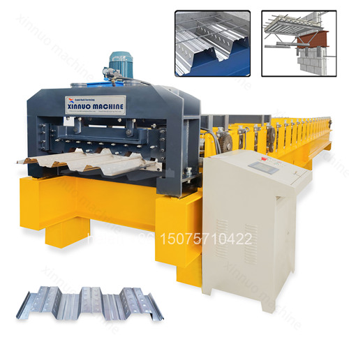
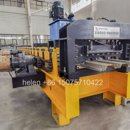
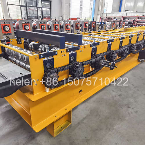
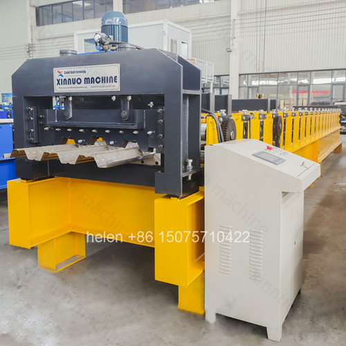
- Pooling jams deep-rib material inside the forming train
- Embossing wheels run larger and faster than adjacent forming wheels
- Clutch release after the dimple row removes the speed mismatch
- Bearing-mounted rear wheels change the action from pulling to pushing
- Reinforcement bars at critical rows hold the shaft under load
- Gear drives raise feed force through the deep forming passes
- Surface quality depends on these mechanisms, not on adjustment
Pooling is the defining operating problem of floor deck production, and it is poorly understood outside the specialist manufacturers who build these machines. It occurs when the strip is unable to move through the forming train at the speed being demanded of it: material bunches and jams between passes, the panel surface is scored by wheels turning against stationary or backing-up material, and the run has to be stopped and the strip extracted by hand. On shallow roof profiles it is rare. On deck profiles with ribs of 50 to 153 mm and material up to 1.5 mm it is the single most likely cause of lost production and rejected panels.
This page explains what causes pooling on a floor decking machine, why the embossing wheel at the heart of every deck profile is the specific origin of the problem, what design measures prevent it, how surface defects beyond pooling arise and are eliminated, what questions to ask when comparing machines from different suppliers, and what operating practices on the shop floor support the machine design. It is written for buyers who want to understand why two machines that look similar on a specification sheet behave very differently in production.
| Root Cause | What Happens in the Machine | Symptom the Operator Sees |
|---|---|---|
| Friction from deep forming | Deep rib profiles create far greater contact area and resistance between the strip and the rolls than shallow roof profiles | The strip slows or stalls in the train, and the drive loads up audibly |
| Excessive shape change per pass | Where the row count is too low, each pass attempts a large deformation and the material cannot advance smoothly | Material bunches at a specific station, consistently the same one on every run |
| Speed mismatch between wheels | Larger-diameter wheels rotate at a different surface speed from smaller adjacent wheels when directly driven from the same chain | Scoring and burnishing marks that appear at regular intervals along the panel |
| Insufficient feed force | The drive cannot pull the material through against the accumulated friction of the deep ribs | The strip stalls partway through, particularly on thicker coil |
| Shaft deflection under load | Forming force bends the shaft slightly, changing the roll gap at the point of maximum load | Inconsistent formation across the panel width, with one side formed less than the other |
| Material variation | Thickness or coating variation in the coil changes the friction and forming load from one coil to the next | A machine that runs cleanly on one coil jams on the next without any setting having been changed |
| Poor tracking at entry | Strip entering off-centre concentrates load on one side of every pair of rolls | Panels that are formed unevenly, with jamming concentrated on one side of the machine |
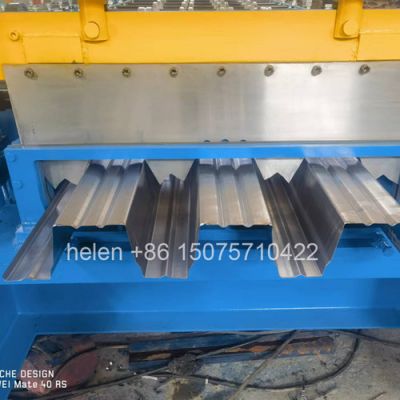
Every floor deck profile carries embossments pressed into the rib faces so that the concrete can grip the steel. These dimples are formed by a dedicated row of embossing wheels, and that row is the specific origin of most pooling.
| Characteristic | Consequence |
|---|---|
| The embossing wheels are larger in diameter than the forming wheels around them | The dimples must be pressed into a rib that already has height, so the wheel that forms them sits deeper and has a larger rolling circumference than the neighbouring forming wheels. |
| Larger diameter means higher surface speed for the same rotation | If driven directly from the same chain as the adjacent smaller wheels, the embossing wheels turn the material faster than the wheels before and after them can accept it. |
| The result is material being pushed into the downstream rolls faster than they can pass it | The strip bunches between the embossing row and the rows that follow — the classic pooling position on a deck machine. |
| The problem is inherent to the profile, not to the operator | Every floor deck profile with embossments presents this geometry, which is why the solution has to be designed into the machine rather than trained into the operator. |
| A machine without a designed solution relies on the operator slowing production | Running below the natural forming speed to keep the embossing row from overrunning the downstream wheels, which directly reduces output and masks the fault. |
| Mechanism | Where It Is Fitted | How It Works | What Happens Without It |
|---|---|---|---|
| Clutch release at the embossing row | Immediately after the dimple wheel row | Once the material has passed through, the clutch disengages, removing drive from the embossing wheels. They then rotate only as the downstream rolls carry the material past them, so their speed is governed by the material rather than by the chain. | The oversized embossing wheels continue to overrun the material, pushing strip into the following rows faster than they can accept it and causing the characteristic jam at that position. |
| Bearing-mounted oversized wheels | Fitted across approximately the rear ten forming rows | The wheels run on internal bearings rather than being keyed solidly to the shaft, so they hold position and rotate freely at the speed the material dictates. | Large-diameter wheels scrub against the material as it passes, which is the principal cause of longitudinal scratching on the panel surface. |
| Reinforcement bars at critical rows | At the embossing row, the main drive, the rib-forming rows, and the sizing rows | Additional reinforcement increases the effective stiffness of the shaft under forming load, so the roll gap is maintained when the load peaks. | The shaft deflects under load, the gap opens at the point of maximum force, and the panel comes out less uniformly formed across its width. |
| Gear drives at selected rows | At the embossing row, ahead of the bearing wheel section, and at the exit rows | Gears transmit higher torque to the rows where the material needs the most feed and pull force, supplementing the chain drive at exactly the points of highest resistance. | Feed force at the most demanding rows is limited by what the chain alone can transmit, and material stalls in thicker gauges. |
| Dual-cylinder floor-level shear | At the discharge end | Two cylinders apply balanced cutting force, and the floor-level position allows finished panels to move to the stacking area without manual lifting. | Uneven cutting force across a wide deep-ribbed panel produces inconsistent ends, and manual handling of heavy panels introduces damage and injury risk. |
| Defect | Origin in the Machine | Commercial Consequence |
|---|---|---|
| Pooling jam | Feed force insufficient for the profile and gauge, or an uncontrolled embossing row | Production stops while the strip is extracted by hand. Repeated jams turn a rated output rate into a theoretical one and consume operator time that is not costed against the order. |
| Longitudinal scratching | Oversized wheels scrubbing the strip as it passes rather than rotating with it | Scratched panels on coated stock are visible in service. On pre-painted deck the marking is permanent, and the panels are rejected or downgraded. |
| Burnishing or polishing marks | Wheel-to-material speed mismatch producing rubbing contact | Particularly conspicuous on coated stock and difficult to explain to a customer who ordered a visible finish. |
| Coating damage at the embossment | Excessive embossing pressure or an incorrectly supported dimple row | Exposes the substrate at the exact point where the concrete will bond, undermining both the appearance and the intended corrosion performance. |
| Uneven formation across the width | Shaft deflection under load, or a load imbalance inherited from poor entry tracking | Panels that do not sit flat when laid, requiring packing or remedial work on site and a complaint that returns to the producer rather than the installer. |
| Twist or waviness along the panel | Insufficient forming rows for the profile depth, or unbalanced drive through the train | Laps do not close properly between adjacent panels, so the floor deck cannot be laid to the specified tolerance without rework. |
| Inconsistent cut ends | Force imbalance at the shear | Some panels stack and lap correctly and others do not, creating sorting work on site and uncertainty about the whole consignment. |
| Condition | Cause | Remedy |
|---|---|---|
| Continuous line along the rib | A burr or damaged point on one wheel face | Identify the station from the position of the mark and inspect the wheel. The regularity of the spacing identifies the wheel responsible. |
| Marks concentrated at the embossment | Embossing pressure too high, or the embossing row unsupported | Review the reinforcement provision at that row rather than reducing dimple depth, which is a structural requirement. |
| Transverse marks at regular intervals | Wheel speed mismatch, typically at the boundary between sizes | Confirm the bearing-mounted wheel provision and the gear drive positions in that part of the train. |
| Marks only on one side | Strip entering off-centre, concentrating load on one side | Correct entry guide alignment. This is a setup fault, not a machine fault, and it is the most common avoidable cause. |
| Marks appearing on thicker coil only | Forming load exceeding what the shaft stiffness can sustain without deflection | Indicates the configuration is at the limit of its thickness range for that profile depth. |
| Pressure marks appearing later in storage | Stacks built without interleaving on coated stock | Interleave as the stack is built rather than after. Once the stack is complete the markings are already set. |
| Damage at the sheet ends | Manual handling between the shear and the stack | Floor-level shearing with gravity discharge removes the handling step and the defect with it. |
| Question | What a Serious Answer Contains |
|---|---|
| How is the embossing row driven? | A specific answer about what happens after the material passes — whether the embossing wheels remain driven or are released and carried by downstream rolls. |
| How many rear rows have bearing-mounted wheels? | A number. A vague reference to "special wheels" without specifying which rows and how many indicates a specification that cannot be verified. |
| Where are the reinforcement bars fitted? | Named rows — embossing, main drive, rib forming, sizing. A general statement that bars are used somewhere in the machine answers nothing. |
| Which rows carry gear drives? | Specific positions. Gear drives fitted at the highest-resistance rows indicate the design has been reasoned through against the profile. |
| How many forming rows for this profile and thickness? | A figure consistent with the rib height. An unusually low row count for a deep profile is the single most reliable indicator of a machine that will pool. |
| What is the motor and chain configuration? | Twin motors and a heavy chain matched to the material thickness. A single motor on a deep-rib deck machine indicates cost reduction at the point where it matters most. |
| How is the shear configured? | Cylinder count, mounting position, and the blade options offered, with the trade-off between them explained rather than presented as an unspecified choice. |
| Which profiles and thicknesses has this configuration run? | Specific references at comparable rib depth and gauge. A machine proven on shallow deck is not evidence of capability on a 153 mm rib. |
| Practice | Effect |
|---|---|
| Run at the speed the profile and gauge allow | Exceeding the speed the forming train can sustain is the most common self-inflicted cause of pooling on a machine that is otherwise correctly designed. |
| Keep the entry guide correctly set | Centred entry distributes the forming load evenly. Off-centre entry concentrates load on one side and produces both jamming and uneven panels. |
| Check the first panel after every changeover | Catches a setting error at the cost of one panel instead of finding it after a full run has been produced off specification. |
| Maintain the lubrication schedule | Chain, gear, and bearing condition determine whether feed force reaches the strip. A neglected drive loses capability gradually and is often blamed on the material. |
| Record the conditions when a jam occurs | Profile, gauge, coil supplier, and speed. A jam traced to one coil supplier is a material issue; a jam traced to one station is a machine issue. |
| Control the coil specification | Thickness tolerance and coating variation in incoming coil change the forming load. Coil that is at the upper limit of the stated gauge range behaves differently from nominal. |
| Do not run outside the specified thickness range | A machine configured for 1.2 mm will not perform reliably on 1.5 mm material without the heavier configuration, regardless of what the profile drawing permits. |
| Parameter | Standard Range |
|---|---|
| Profile type | Open trapezoidal deck and closed re-entrant deck, produced to the buyer's profile drawing or a matched standard section |
| Effective coverage width | 688 – 1025 mm across the standard families; wider by drawing specification |
| Rib height | 39 – 153 mm depending on profile class |
| Forming rows | 18 – 36 rows, selected against rib height, section type, and material thickness |
| Frame | 400H – 450H welded H-section with 10 mm flange thickness and a 18 – 25 mm mid plate |
| Shaft | Φ90 – 115 mm round bar, rough turned then precision ground |
| Forming wheels | 45# forged steel, quenched to HRC 45 – 50, finish turned, keyed, polished, and chrome plated |
| Embossment row | Dedicated dimple wheel row with a clutch arrangement that releases drive once material has passed |
| Rear forming rows | Bearing-mounted oversized wheels fitted across approximately the rear ten rows |
| Reinforcement provision | Reinforcement bars at the embossing row, main drive, rib-forming rows, and sizing rows |
| Gear drives | Fitted at the embossing row, ahead of the bearing-mounted wheel section, and at the exit rows |
| Transmission | 2 inch external roller chain standard, 2.5 inch for the heaviest profiles |
| Motor configuration | 2 × 11 kW standard, 2 × 15 kW heavy, 2 × 22 kW above 1.5 mm material |
| Shear | Dual-cylinder hydraulic shear at floor level for balanced force and gravity-assisted panel discharge |
| Blade options | Three-blade for the cleanest edge with approximately 10 mm trim waste, or two-blade for zero waste with negligible edge deformation |
| Material capability | 0.8 – 1.5 mm standard; galvanized, aluminium-zinc coated, and pre-painted coil |
| Forming speed | 8 – 18 m/min depending on profile depth and material thickness |
| Cut length tolerance | ±1.5 mm |
| Control system | PLC with colour touchscreen HMI, sheet count control, and stored recipe banks |
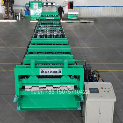
| Line length | Approximately 22 m overall, with a forming unit of about 14.5 m and a forming unit width of about 2.75 m |
| Electrical supply | 380 V / 50 Hz / 3-phase standard; alternative voltages and frequencies by destination |
| Certification | CE marking and ISO 9001:2015 compliant manufacturing |
Coil loading on the decoiler, strip entry through the guide, progressive forming across the roll train with embossment at the dimple row, sizing over the final passes, length measurement, dual-cylinder cutting at floor level, and gravity discharge to the stacking position follow the established sequence, with the anti-pooling provision acting continuously through the train rather than requiring operator intervention.
Hebei Xinnuo is a professional cold roll forming machinery manufacturer with 20+ years of experience. We specialize in C/Z purlin machines, roof panel roll formers, floor deck machines, and custom profile solutions — exported to 50+ countries worldwide.