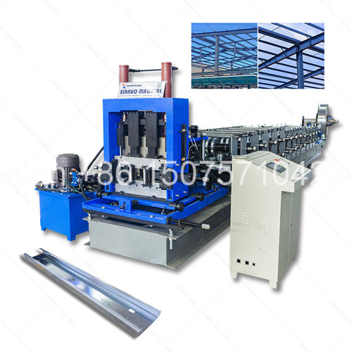
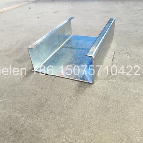
Purlin Roll Forming Machine — Automatic Cold Roll Forming Production Line for Structural Steel Purlins
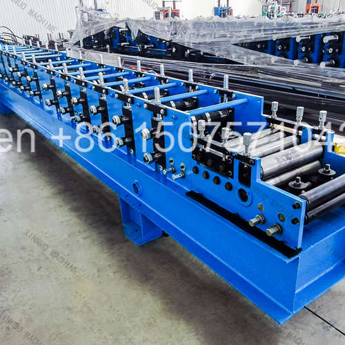
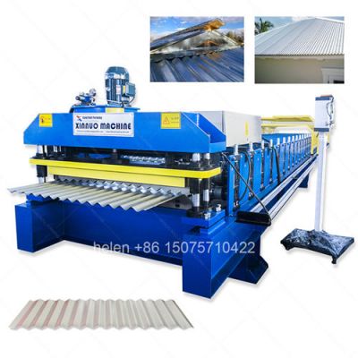
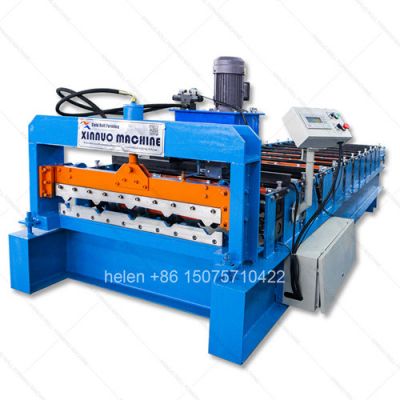
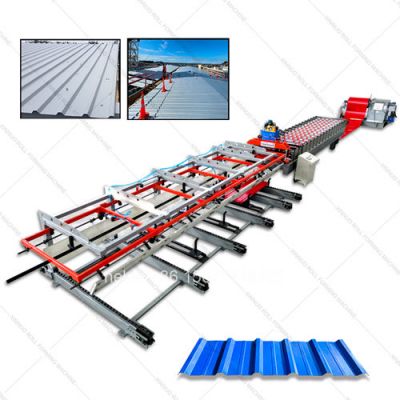
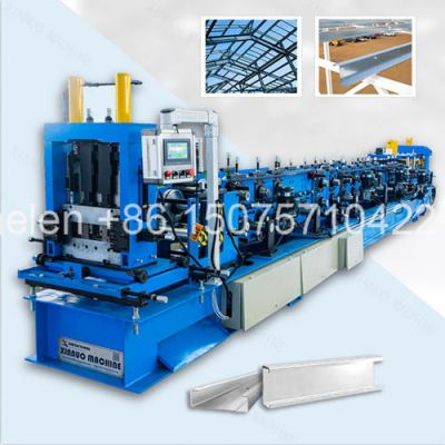
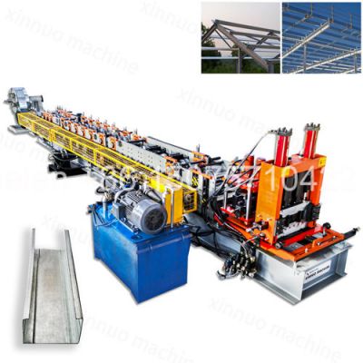
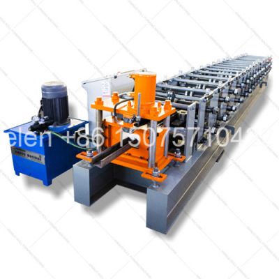
This automatic purlin roll forming machine converts flat galvanized or cold-rolled steel coils into finished structural purlins through a continuous cold roll forming process. The machine progressively bends the steel strip through multiple roller stations — each station incrementally shaping the material closer to the final C or Z cross-section — without heating, cutting, or welding during forming. This cold-working method preserves the material's zinc coating integrity, maintains consistent mechanical properties throughout the profile, and eliminates the thermal distortion risks associated with hot-forming or press-brake alternatives. The result is a high-precision structural purlin ready for immediate use in steel frame buildings, with dimensional accuracy controlled at every roller pass.
Cold Roll Forming Process Explained
| Phase |
Process Stage |
What Happens |
| 1 |
Coil Decoiling |
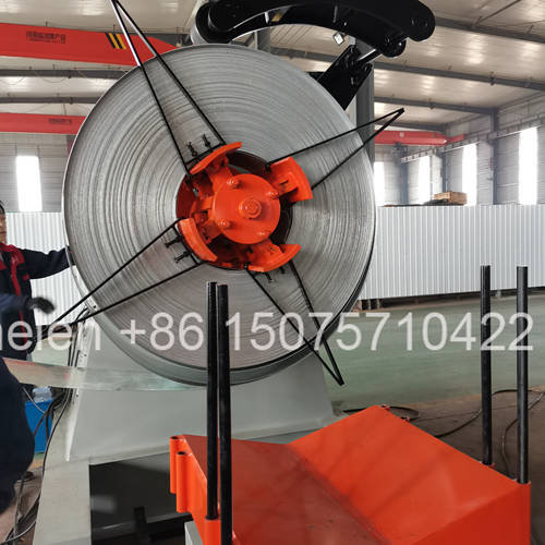
Steel coil mounted on hydraulic decoiler; strip fed at controlled tension into the line |
| 2 |
Strip Flattening |
7-roller leveling cassette removes coil-set curvature, producing a flat strip ready for forming |
| 3 |
Pre-Punching |
Hydraulic punch unit creates bolt holes and service openings at programmed positions before the strip enters forming |
| 4 |
Progressive Forming |
Strip passes through 14-20 paired roller stations; each station bends the profile a few degrees more than the last |
| 5 |
Sizing & Straightening |
Final roller pass corrects spring-back, twist, and camber to achieve finished dimensional tolerances |
| 6 |
Cut-to-Length |
Hydraulic or flying shear cuts the continuous profile at the programmed length with automatic blade return |
| 7 |
Run-Out & Collection |
Finished purlins slide onto the roller conveyor table for manual or automated stacking |
Core Machine Architecture
| System |
Description |
| Machine Bed |
Welded structural steel base frame, stress-relief annealed, CNC line-bored for shaft mounting accuracy. Mounted on anti-vibration pads for stable long-term operation. |
| Forming Frame |
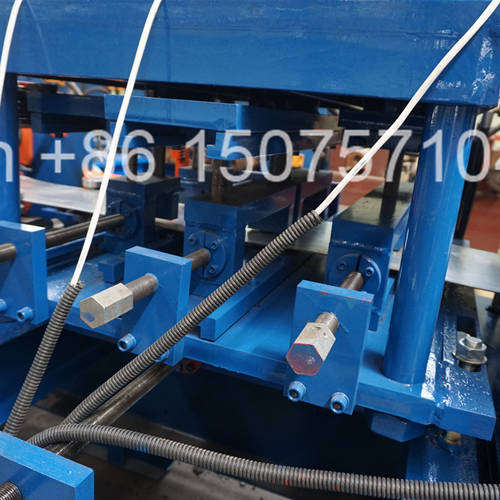
Vertical steel plate housings (牌坊 or H-beam type), precision-machined on 12-meter CNC gantry mill. Each station carries a matched top-and-bottom roller pair on precision bearings. |
| Roller Shafts |
40Cr alloy steel shafts, rough-turned, precision-ground to h7 tolerance, then hard chrome plated. Supported by heavy-duty spherical roller bearings in sealed housings. |
| Forming Rollers |
GCr15 bearing steel or Cr12MoV alloy rollers, CNC profile-turned, vacuum heat-treated to HRC 58-62, hard chrome finished. Split-design rollers allow individual replacement. |
| Drive Train |
Main motor → gear reducer → distribution gearbox → chain drive to each station. Dual-strand roller chain with automatic tensioners ensures synchronized rotation across all stations. |
| Electrical System |
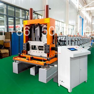
Siemens or Delta PLC controller, 10-inch HMI touchscreen, VFD motor drive, labeled terminal blocks with pre-wired harnesses. All sensors and limit switches pre-calibrated. |
| Hydraulic System |
Separate power pack with oil reservoir, pressure-compensated pump, manifold valves, and filtered return. Supplies shear cylinder, punch cylinders, and decoiler expansion. |
| Safety Guarding |
Perimeter safety fencing with interlocked access gates, emergency stop buttons at operator station and line end, light curtains optional for high-speed configurations. |
Machine Configuration by Production Volume
| Production Level |
Forming Speed |
Rows |
Motor Power |
Shear Type |
Annual Output Estimate |
| Light Production |
4-8 m/min |
12-14 |
5.5-11 KW |
Hydraulic stop-cut |
500-1,000 tons |
| Standard Production |
6-12 m/min |
15-18 |
15-22 KW |
Hydraulic stop-cut |
1,000-2,500 tons |
| High Volume Production |
8-15 m/min |
16-20 |
22-30 KW servo |
Flying shear |
2,500-5,000 tons |
| Industrial Scale |
10-18 m/min |
20-26 |
30-55 KW servo |
Servo flying shear |
5,000+ tons |
Electrical Control System Features
| Feature |
Benefit |
| 10-inch Color Touchscreen HMI |
Visual machine status, real-time production counter, fault alarm display |
| Profile Recipe Storage |
Save 50+ profile configurations; recall with one touch — no recalibration needed |
| Automatic Length Programming |
Enter target quantity and length; machine auto-runs and stops at completion |
| Multi-Motor Synchronized Axis Control |
PLC coordinates width, height, lip, and gap motors with encoder feedback loop |
| Production Data Logging |
Records total output, run hours, and stop events for OEE analysis |
| Remote Access Ready |
Ethernet port enables remote diagnostics and PLC program updates |
| Multi-Language Interface |
English, Spanish, Russian, Arabic, French, Portuguese, and others available |
Material Input Specifications
| Input Parameter |
Standard Range |
Notes |
| Coil Inner Diameter |
Φ508 mm (standard) / Φ610 mm (optional) |
Decoiler mandrel matched to customer coil inventory |
| Coil Outer Diameter |
Up to Φ1,500 mm |
Larger O.D. available with A-frame decoiler option |
| Coil Weight |
Up to 5 tons (standard) / Up to 8 tons (heavy-duty) |
Cantilever or tripod decoiler selected accordingly |
| Strip Width |
Calculated per profile: W + 2H + 2L + trimming allowance |
Slit-to-width coil recommended for best edge quality |
| Strip Thickness Tolerance |
±0.05 mm (commercial grade) |
Thicker tolerance band may require gap adjustment |
| Surface Condition |
Clean, dry, free of rust and mill scale |
Oiled surfaces acceptable; heavy oil may need pre-cleaning |
Installation and Commissioning Requirements
| Requirement |
Specification |
| Foundation Type |
Reinforced concrete floor, minimum 150mm thickness, flat to ±3mm over machine length |
| Power Supply |
3-phase, 380V/50Hz or 440V/60Hz (custom voltages available), dedicated circuit with isolator |
| Compressed Air |
0.6-0.8 MPa, dry and filtered, for pneumatic brake and optional marking systems |
| Overhead Crane |
Minimum 5-ton capacity for machine positioning and coil loading |
| Installation Duration |
5-7 working days including mechanical alignment, electrical connection, and test runs |
| Operator Requirement |
2 persons: one HMI operator, one material handler / stacker |
Routine Maintenance Schedule
| Frequency |
Task |
Responsible |
| Daily |
Clean roller surfaces, check oil level, inspect chain tension, verify emergency stops |
Operator |
| Weekly |
Grease all bearing points, check hydraulic hoses for leaks, verify sensor alignment |
Operator |
| Monthly |
Inspect chain wear and sprocket teeth, check electrical connections, verify shear blade sharpness |
Maintenance technician |
| Quarterly |
Replace hydraulic oil filter, check gearbox oil condition, inspect roller die wear pattern |
Maintenance technician |
| Annually |
Full hydraulic oil change, gearbox oil change, comprehensive roller die inspection, PLC backup |
Service engineer |
Quality Control Protocol During Manufacturing
- Incoming steel plate inspection for chemical composition and mechanical properties before fabrication
- Welded frame undergoes ultrasonic testing on critical load-bearing joints
- Stress-relief annealing cycle verified by furnace temperature chart recorder
- CNC machining dimensions verified with laser tracker across full 12-meter bed length
- Each roller die measured on CMM (coordinate measuring machine) against CAD profile data
- Shaft runout checked on precision V-blocks with dial indicator — maximum 0.02mm TIR
- Assembled machine runs dry cycle test for 4 continuous hours before customer acceptance
- Final production test processes actual customer-specified material to verify first-piece quality
Packaging and Shipping Protection
- All machined surfaces coated with anti-rust oil and wrapped in VCI (volatile corrosion inhibitor) film
- Roller dies individually wrapped and packed in reinforced wooden crates with foam inserts
- Control cabinet sealed in moisture-barrier bag with desiccant packs before crating
- Main machine frame secured to steel shipping skids with bolted tie-downs, not banding
- Container loading plan prepared in advance with weight distribution verified for sea freight
- Spare parts kit and tool box packed separately with packing list for customs clearance
- Full photo documentation of packed condition provided before container sealing