helen@hbxinnuorollforming.com
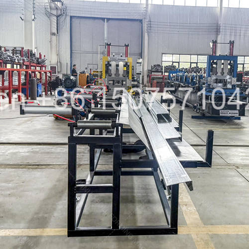
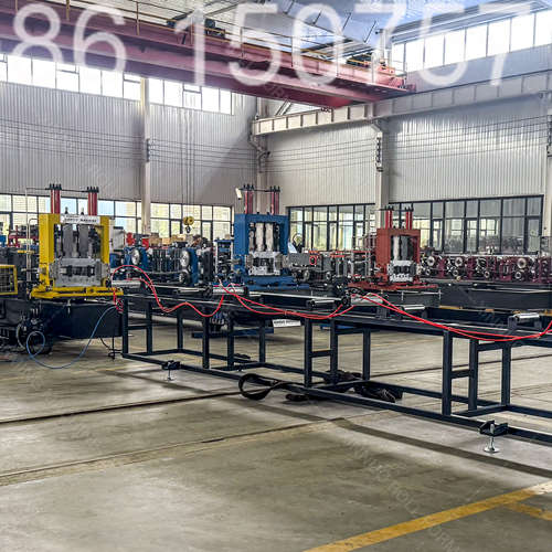
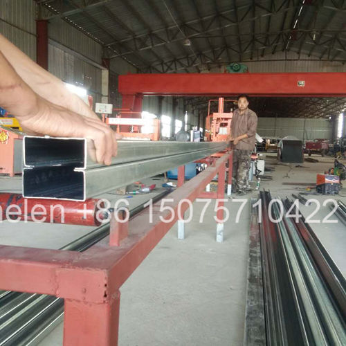
- Progressive roll forming technology shapes steel without heating or cutting
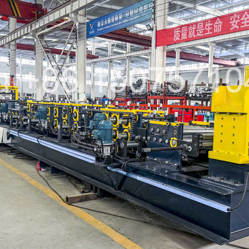
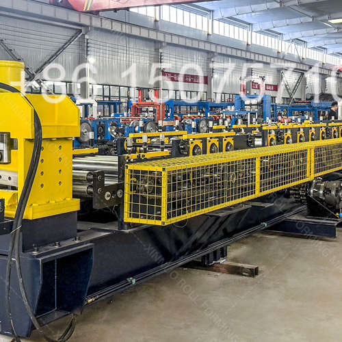
- CNC-designed flower pattern ensures gradual bend across each station
- Matched top-bottom roller pairs with precision ground profile geometry
- Independent station adjustment for fine-tuning spring-back compensation
- Universal shaft design accepts interchangeable roller sets for new profiles
- Anti-friction roller surface treatment prevents zinc coating pick-up
- Digital forming speed control synchronized with punch and shear timing
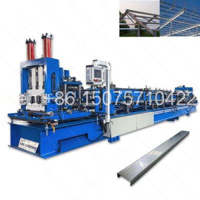
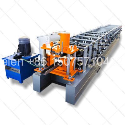
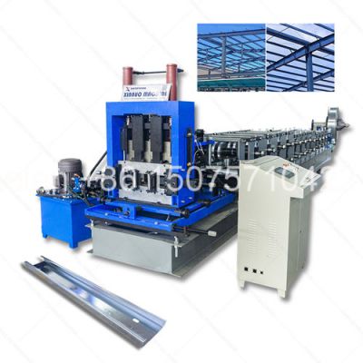
This purlin roll former is a specialized cold roll forming machine that progressively transforms flat steel strip into finished C, Z, and CZ structural purlins through a scientifically calculated sequence of bending operations. The term "roll former" specifically refers to the forming section — the heart of any purlin production line — where matched pairs of hardened steel rollers, arranged in a carefully engineered flower pattern, incrementally bend the material from a flat strip into the final purlin cross-section. Unlike press brakes that form the entire profile in one stroke, or stamping that cuts and forms simultaneously, roll forming applies controlled, localized deformation at each roller station, preserving material integrity, maintaining coating adhesion, and producing consistent profile geometry across unlimited continuous lengths.
Engineering PrincipleExplanationPractical Impact
Incremental DeformationEach roller station bends the strip only 8-15 degrees from the previous station. A full 90-degree flange bend is achieved across 6-8 stations, not one.Material never exceeds its forming limit; no cracking, thinning, or coating damage at bend lines
Flower Pattern DesignEngineers plot the cross-section at every station, starting from flat and ending at the finished profile — the overlay resembles a blooming flower, hence the nameProper flower design eliminates edge wave, twist, and camber — the three most common forming defects
Spring-Back CompensationMetal naturally springs back slightly after bending. Roll forming over-bends by 2-5 degrees so the material relaxes to the exact target angleFinal profile dimensions accurate to ±0.5mm without post-forming correction
Neutral Axis PositioningBending occurs around the material's neutral axis where neither compression nor tension exists. Roller geometry is designed around this axisNo residual stress in the formed profile; purlins stay straight without twisting over time
Material Flow ControlSide rollers and guide rollers at each station constrain the strip laterally, preventing walk-off and maintaining consistent lip dimensionsLip length variation under ±0.5mm across the entire production run
Frame TypeConstructionRigidityMachiningBest ApplicationCost Signal
H-Beam WeldedStructural H-beam steel, welded base, bolt-on side plates per stationGood for light gaugeIndividual station plates milled separatelyManual C purlin, ≤1.5mm thicknessMost economical
Solid Plate Side-FrameContinuous 30-35mm steel plates, welded to base, line-bored as one unitVery good for medium gaugeComplete frame line-bored on 12m CNC millComputer C purlin, ≤2.5mm thicknessMid-range
Archway (牌坊式) FrameIndividual 40mm arch-shaped plates, vertical ribs, precision pin-alignedExcellent for heavy gaugeEach plate CNC-machined individually; assembled on precision-ground railsCZ integrated, ≤3.0mm thicknessPremium
Heavy Archway Frame50mm thick arch plates, double ribs, hardened alignment pins, bolted cross-tiesMaximum for structural gaugeIndividual plate machining; laser-aligned during assemblyCZU flagship, ≤5.0mm thickness, high-tensile steelFlagship
Station GroupStationsForming ActionBend Angle per StationCumulative Angle
Entry GuideStation 1Strip centering and initial edge guidance; no bending0°0°
Lip Pre-FormStations 2-4Outer edges bent upward to form both lips simultaneously; symmetrical to avoid walk-off15° per station0° → 45°
Flange FormingStations 5-10Both side flanges bent upward in progressive steps; lip angle maintained as flange rises10-12° per station45° → 90°
Sizing and FinishStations 11-14Final flange angle calibration; over-bend for spring-back; web flatness correction2-5° over-bend90° → 92-95° (relaxes to 90°)
Straightening PassStation 15Turk's head unit — independently adjustable horizontal and vertical correction rollersFinal alignmentFinal profile
Roller ComponentMaterial GradeHardnessSurface TreatmentPurpose
Standard Forming RollersGCr15 bearing steelHRC 58-62Hard chrome plate 0.03-0.05mmGeneral forming; corrosion resistance; smooth surface prevents zinc pick-up
High-Wear Edge RollersCr12MoV cold-work die steelHRC 60-63Hard chrome plate 0.05mmLip forming zone where friction is highest; 3× service life vs standard
Side Guide RollersCr12MoV or GCr15HRC 58-62Hard chrome or nitridedLateral strip control; must resist abrasive edge contact
Straightening RollsGCr15 or 9Cr2MoHRC 56-60Polished to Ra 0.2μmFinal profile correction; mirror finish prevents surface marking on finished purlin
Entry Guide Rolls45# steel or GCr15HRC 45-55Induction hardened surfaceLow-wear application; cost-effective material choice
Drive ComponentConfigurationEngineering Detail
Main Drive MotorGeared motor / hydraulic motor / servo motorSelected by production speed and precision requirements; servo offers electronic gearing for perfect synchronization
Primary Gear ReducerHelical gearbox, oil-bath lubricatedReduces motor RPM to forming speed; hardened and ground gears for quiet operation and long life
Distribution GearboxMultiple output shafts, 1:1 ratio to each stationSplits drive power equally to all stations through universal joint shafts or chain sprockets
Top-Bottom Shaft SynchronizationMatched gear pair per station (1:1 ratio)Identical-diameter gears on top and bottom shafts ensure both rollers rotate at exactly the same surface speed — critical to prevent material scrubbing
Chain Drive SystemDual-strand roller chain with automatic tensionersChains sized by load: 1.5-inch for light, 2-inch for standard, 2.5-inch for heavy-duty; hardened sprocket teeth resist wear
Universal Joint ShaftsCardan shaft with telescopic sectionAlternative to chain drive for premium machines; zero backlash, no elongation, maintenance-free operation
Adjustment MethodMechanismPrecisionChangeover SpeedApplication Tier
Manual Shim AdjustmentAdd or remove precision-ground shim plates between bearing housing and frame±0.1mm per shim5-10 minutes per stationEntry-level fixed-size machines
Manual Screw AdjustmentThreaded adjustment screw with lock nut and dial indicator readout±0.05mm1-2 minutes per stationManual multi-size machines
Motorized Gap AdjustmentElectric motor with encoder feedback drives lead screw; HMI displays gap value±0.02mmUnder 30 seconds — all stations simultaneouslyComputer-controlled machines
Servo-Controlled GapAC servo motor per station with absolute encoder; closed-loop position control±0.01mmUnder 15 seconds — recipe recall, no manual check neededCZ and CZU premium machines
Material ThicknessMax Forming SpeedLimiting FactorRecommendation
0.7-1.0 mm18-20 m/minStrip buckling risk at entry; edge wave formationReduce to 12-15 m/min for profiles with deep draw or narrow lips
1.2-1.5 mm12-18 m/minSmooth forming; machine rigidity typically not the limitIdeal thickness range; run at rated speed with standard roller gap
1.8-2.0 mm8-12 m/minMotor power becomes limiting; roller contact pressure increasesEnsure adequate motor KW; check roller surface for heat build-up on long runs
2.3-2.5 mm6-10 m/minSpring-back increases; may need extra over-bend stationVerify straightening unit capacity; consider additional forming pass
2.8-3.0 mm4-8 m/minFrame deflection under high forming loads; drive chain stressMust use archway frame; upgrade chain to 2.5-inch; verify motor torque curve
3.5-5.0 mm2-5 m/minExtreme forming forces; requires heavy archway frame and large shaftsCZU flagship only; 50mm frame plates, Φ120 shafts, 55KW servo minimum
Alignment ParameterStandard TolerancePremium ToleranceMeasurement Method
Shaft Parallelism (vertical plane)≤0.05mm across 1,000mm≤0.03mm across 1,000mmDial indicator on precision straight edge across shaft tops
Shaft Parallelism (horizontal plane)≤0.05mm across 1,000mm≤0.03mm across 1,000mmLaser alignment tool or piano wire with feeler gauge
Shaft Runout (TIR)≤0.03mm total indicated runout≤0.02mm TIRDial indicator on shaft journal; rotate shaft through 360 degrees
Roller Concentricity≤0.03mm radial runout≤0.02mm radial runoutDial indicator on roller OD; rotate on precision mandrel
Station-to-Station Alignment≤0.10mm centerline deviation≤0.05mm centerline deviationLaser tracker across all stations; or piano wire with microscope
Bearing Housing Bore Alignment≤0.02mm across bore length≤0.01mm across bore lengthLine-bored as single setup on CNC mill; checked with bore gauge
Wear PatternVisual IndicatorRoot CauseCorrective ActionPrevention
Peripheral GroovingVisible groove worn into roller OD along material contact lineAbrasive particles on strip surface; insufficient cleaning before formingPolish out minor grooving; replace roller if groove depth exceeds 0.2mmInstall strip wiping system before entry; use clean coil stock
Edge ChippingSmall chips missing from roller edge radiusMaterial strip edge burrs cutting into roller; misaligned entry guidesReplace damaged roller; dress strip edges if recurringUse slit-to-width coil with deburred edges; maintain guide alignment
Zinc Build-UpGrey metallic deposit on roller surface in forming zoneGalvanized coating transferring to roller under high pressure and temperatureClean with brass brush or chemical zinc remover; polish roller surfaceUse rollers with polished chrome finish; reduce forming speed if overheating
Uneven Wear BandWear concentrated on one side of roller profileStrip not centered through machine; side guide misalignmentReverse roller if design allows; center strip path; check all guidesRegular laser alignment check of strip centerline through all stations
Surface PittingSmall craters or pits visible on roller forming surfaceCorrosion from improper storage; chemical attack from contaminated coolantReplace pitted rollers — pitting marks transfer to finished productStore spare rollers with VCI paper and oil coating in dry environment
Upgrade PathFromToFeasibilityBenefit
Add Additional Forming Stations12-14 station machine16-18 station machinePossible if base frame is long enough; requires new rollers and shaft extensionsHandles thicker material; reduces spring-back; smoother profile surface
Hydraulic to Servo Motor ConversionHydraulic motor driveAC servo motor with driveFeasible; requires motor mount modification, servo drive, and PLC program updateRecipe storage; precise speed control; energy saving; quieter operation
Manual to Motorized AdjustmentManual handwheel adjustmentMotorized with encoder feedbackRetrofit possible with bolt-on motor brackets and wiring to control cabinetFaster changeover; HMI position display; reduces operator skill requirement
Stop-Cut to Flying ShearHydraulic stop-cut shearFlying/track shear systemMajor modification; requires forming unit extension, track system, and control upgradeContinuous production; 15-20% output increase; better cut accuracy
New Profile Roller SetExisting profile onlyAdditional profile capabilityEngineering required for new flower pattern; 3-4 weeks for new roller set fabricationExpand product range without buying second machine