helen@hbxinnuorollforming.com
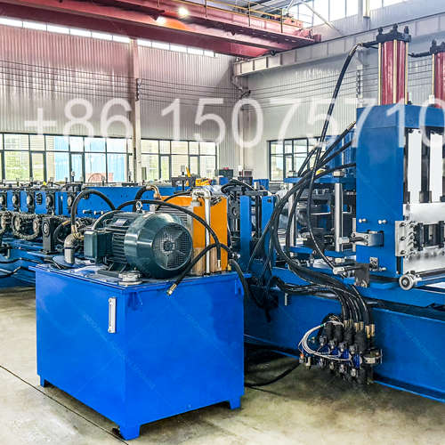
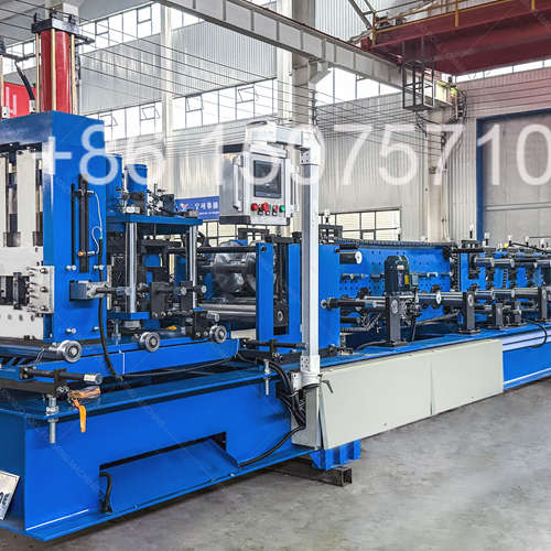
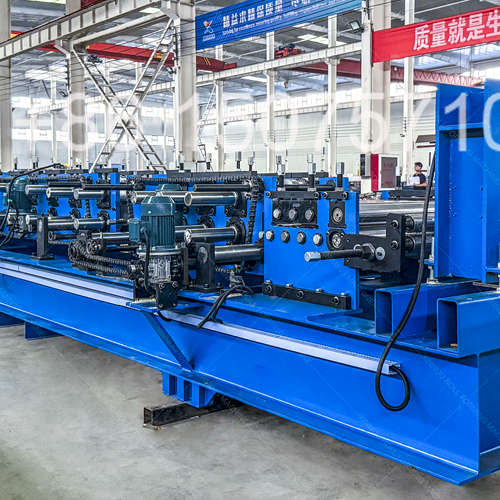
- Complete purlin manufacturing system from raw coil to finished product
- Rapid profile changeover with digital position memory recall
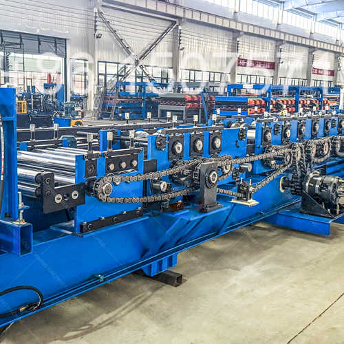
- Heavy structural base frame with precision laser-aligned bearing seats
- Independent hydraulic circuits for punch shear and decoiler operation
- Automatic lubrication system delivers metered oil to every bearing
- Built-in production diagnostics with fault code display and history log
- Pre-tested fully assembled before disassembly for container shipment
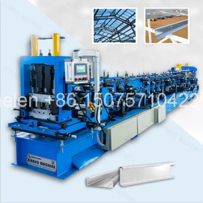
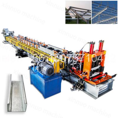
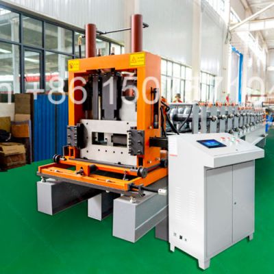
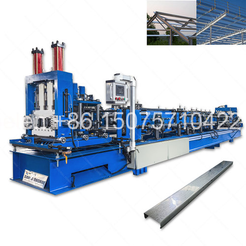
This purlin making machine is a fully integrated cold roll forming manufacturing system that converts flat steel coil into finished structural purlins through a continuous automated production process. Designed from the ground up as a complete factory solution rather than a standalone forming unit, the machine encompasses every stage of purlin manufacturing — material handling, strip preparation, hole punching, progressive forming, precision cutting, and finished product collection. The system architecture follows industrial automation principles with independent subsystems coordinated by a central PLC controller, allowing each module to be monitored, diagnosed, and maintained separately while operating as a synchronized whole. For steel structure fabricators, building material suppliers, and construction companies, this machine represents the core production asset that transforms purchased coil stock into value-added structural components with full control over quality, schedule, and cost.
| Phase | Manufacturing Step | Quality Control Gate |
|---|---|---|
| 1 | Steel Plate Procurement | Mill test certificate verification; ultrasonic thickness check on all plates above 30mm |
| 2 | Frame Welding | CO2 gas-shielded process; weld seam visual inspection; magnetic particle testing on critical joints |
| 3 | Stress Relief Annealing | Furnace cycle verified by temperature chart recorder; hardness test post-anneal to confirm stress removal |
| 4 | CNC Machining | 12-meter gantry mill; laser tracker dimensional verification; surface finish measurement on bearing seats |
| 5 | Shaft Manufacturing | 40Cr billet → rough turn → precision grind → chrome plate → final polish; runout check on V-blocks |
| 6 | Roller Die Fabrication | GCr15 forging → rough turn → vacuum quench → temper → finish turn → keyway → chrome plate; CMM inspection |
| 7 | Sub-Assembly Build | Bearings pressed and measured; chain sprockets aligned with laser; hydraulic circuits pressure-tested |
| 8 | Main Assembly | Shafts installed and aligned; roller dies mounted sequentially; drive chain tensioned; all fasteners torqued |
| 9 | Electrical Integration | Control cabinet wired per schematic; sensors calibrated; safety circuit verified; HMI program loaded |
| 10 | Dry Run Test | 4-hour continuous unloaded operation; all stations monitored for temperature, noise, and vibration |
| 11 | Production Test | Customer-specified material run; first-piece dimensional inspection; 20-piece sample measured for consistency |
| 12 | Surface Treatment | Shot blast to SA 2.5; electrostatic powder coat; oven cure; coating thickness and adhesion verified |
| 13 | Pre-Shipment Inspection | Final dimensional check; function test of all subsystems; documentation package completeness verification |
| Workshop Condition | Recommended Configuration | Reasoning |
|---|---|---|
| Limited floor space (under 20m length) | 13-row CU compact line, ~17m total | Shortest productive line; fits smaller factories without sacrificing output |
| No overhead crane available | Machine with automatic coil car + 3-ton cantilever decoiler | Eliminates crane dependency; coil loaded at floor level by forklift or pallet truck |
| Unstable power grid / voltage fluctuation | Hydraulic motor drive + voltage stabilizer + phase protection relay | Hydraulic drive more tolerant of power variation than servo; protection prevents motor damage |
| Dusty or outdoor-adjacent environment | Sealed bearings throughout + heavy-duty chain guards + IP54 control cabinet | Contamination protection extends bearing and chain life in harsh conditions |
| Multi-shift 24-hour operation planned | Full-auto CZU with servo drive + automatic stacker + central lubrication | Maximum automation reduces operator fatigue; auto lube ensures bearing life under continuous duty |
| Remote location, limited technical support | Simple manual C machine + comprehensive spare parts kit + detailed video training | Mechanical simplicity means local mechanics can maintain; less electronics to troubleshoot |
| High ambient temperature (over 40°C) | Oversized hydraulic oil cooler + ventilated control cabinet with active cooling fan | Prevents hydraulic oil overheating and PLC thermal shutdown in hot climates |
| Component | Economy Tier | Standard Tier | Professional Tier | Industrial Tier |
|---|---|---|---|---|
| Decoiler Type | Manual expansion, 3-ton | Manual expansion, 5-ton | Hydraulic expansion, 5-ton | Hydraulic expansion, 8-ton A-frame |
| Leveling Rollers | 5-roller, fixed upper | 7-roller, adjustable upper | 7-roller, motorized upper | 9-roller, servo-controlled |
| Forming Frame | 300H welded beam | 350-400H welded beam | 400-450H archway plate | 450-500H heavy archway |
| Forming Shafts | Φ65-75, 45# steel | Φ80-95, 40Cr steel | Φ90-100, 40Cr + chrome | Φ100-120, 40Cr + chrome |
| Shaft Bearings | Deep groove ball | Spherical roller, standard | Spherical roller, heavy series | Tapered roller, matched pairs |
| Drive Motor | 5.5-7.5 KW geared | 11-22 KW geared | 22-30 KW hydraulic | 30-55 KW servo |
| Transmission Chain | 1.5-inch single strand | 2-inch single strand | 2-inch dual strand | 2.5-inch dual strand |
| Punch Capacity | Optional external | Single station, 25-ton | Dual station, 40-ton | Multi-die, 63-ton each |
| Shear System | Manual / basic hydraulic | Hydraulic stop-cut | Hydraulic flying cut | Servo flying cut |
| Control PLC | Basic relay / mini PLC | Delta / domestic brand | Delta / Siemens | Siemens S7-1200/1500 |
| HMI Display | Push-button panel | 7-inch touchscreen | 10-inch touchscreen | 12-inch touchscreen + remote |
| Tooling Item | Quantity per Machine | Storage Method | Service Life Guideline | Replacement Indicator |
|---|---|---|---|---|
| Forming Roller Die Set | 2 per station (top + bottom) | Numbered rack, individual slots | 5,000-10,000 tons production | Profile dimension drift; surface roughness on formed product |
| Side Guide Rollers | 1-2 per station | Mounted on adjustable brackets | 3,000-5,000 tons | Excessive free play; grooving on contact surface |
| Straightening Rolls | 4 total (2H + 2V) | Mounted on Turk's head unit | 4,000-7,000 tons | Inability to correct twist or camber fully |
| Punch Die Set | Per hole pattern | Labeled storage cabinet | 50,000-100,000 strokes | Burr formation on hole edge; increased punching noise |
| Shear Blade Set | 1 upper + 1 lower | Installed on shear unit | 20,000-40,000 cuts | Burr on cut edge; angled cut instead of square |
| Leveling Rolls | 7 total (3 upper + 4 lower) | Installed in leveling cassette | 8,000-12,000 tons | Strip not fully flattening; uneven wear pattern visible |
| Chain Sprockets | 2 per station | Mounted on shaft ends | 3-5 years normal production | Hook-shaped tooth wear; chain skipping under load |
| System Layer | Components | Function |
|---|---|---|
| Power Distribution | Main circuit breaker, phase monitor, voltage transformer, distribution busbars | Receives incoming factory supply; distributes to motor drives, control circuits, and auxiliary power |
| Motor Control | Variable frequency drives, soft starters, contactors, thermal overload relays | Controls speed and direction of main drive, adjustment motors, and hydraulic pump motor |
| PLC Controller | CPU module, digital I/O modules, analog input module, high-speed counter module | Executes machine logic; processes sensor inputs; coordinates all subsystem timing |
| HMI Interface | Touchscreen panel, USB port, Ethernet port | Operator input and production monitoring; recipe management; alarm display and history |
| Sensors and Feedback | Rotary encoders, proximity switches, limit switches, pressure transducers, temperature sensors | Provides real-time position, pressure, and status data to PLC for closed-loop control |
| Safety Circuit | Safety relay, emergency stop buttons, interlock switches, light curtain interface | Hardwired safety loop independent of PLC; guarantees immediate stop on any safety event |
| Auxiliary Systems | Lighting transformer, cooling fans, lubrication pump controller, beacon and alarm driver | Supports non-production systems essential for machine operation and operator safety |
| Calculation Factor | Formula or Value | Example (Standard C Machine) |
|---|---|---|
| Line Speed at Given Thickness | Rated speed × thickness factor (1.0 at 1.5mm, 0.7 at 2.5mm) | 10 m/min × 1.0 = 10 m/min at 1.5mm |
| Effective Production Rate | Line speed × efficiency factor (0.85 stop-cut, 0.98 flying shear) | 10 × 0.85 = 8.5 effective m/min |
| Meters per Hour | Effective rate × 60 minutes | 8.5 × 60 = 510 meters per hour |
| Tons per Hour (1.5mm C100×50) | Meters/hour × kg per meter ÷ 1,000 | 510 × 2.5 ÷ 1,000 = 1.28 tons/hour |
| Daily Output (8-hour shift) | Tons/hour × 8 × utilization factor (0.80) | 1.28 × 8 × 0.80 = 8.2 tons/day |
| Monthly Output (22 days) | Tons/day × 22 working days | 8.2 × 22 = 180 tons/month |
| Annual Capacity (single shift) | Tons/month × 12 months | 180 × 12 = 2,160 tons/year |
| Waste Source | Typical Loss Rate | Reduction Strategy | Target Improvement |
|---|---|---|---|
| Coil end scrap (tail and head) | 1-2% per coil | Use coil-end welding station; optimize coil order weight to match production batch | Reduce to 0.3-0.5% |
| Setup and trial pieces | 2-4 pieces per changeover | Recipe memory eliminates trial-and-error; first piece is finished product | Reduce to zero trial waste |
| Length overcut allowance | 5-10mm per piece | Encoder-based servo feed with automatic kerf compensation | Reduce to 2-3mm per piece |
| Rejected pieces from defects | 0.5-2% of production | Real-time straightening adjustment; preventive roller maintenance schedule | Reduce to under 0.5% |
| Width trim from slit coil | 0-3mm per edge | Order coil slit to exact developed width; eliminate trim station if possible | Eliminate trim scrap entirely |
| Coil handling damage | 0.1-0.5% per coil | Padded coil car contact surfaces; proper coil storage on V-cradles not flat floor | Reduce to near zero |
| Week | Activity | Responsible Party | Deliverable |
|---|---|---|---|
| 1-5 | Machine manufacturing and assembly | Factory production team | Completed machine ready for testing |
| 5 | Factory acceptance test with customer material | QC team + customer (on-site or video) | Signed acceptance report; test samples retained |
| 5-6 | Disassembly, surface treatment, and packing | Factory packing team | Machine packed in shipping configuration; photo documentation |
| 6-7 | Container loading and customs clearance | Factory + freight forwarder | Bill of lading; commercial invoice; packing list; certificate of origin |
| 7-11 | Ocean freight transit to destination port | Shipping line | Vessel tracking updates; estimated arrival notice |
| 11-12 | Destination customs clearance and delivery to factory | Buyer + local customs broker | Machine delivered to installation site |
| 12-13 | Mechanical assembly and alignment | Installation engineer + local team | Machine assembled on foundation; shafts aligned |
| 13 | Electrical connection and system check | Installation engineer | All systems powered; sensors calibrated; safety circuit verified |
| 13-14 | Commissioning and production test | Installation engineer + operator team | Machine producing at specified speed and quality |
| 14 | Operator training and handover | Installation engineer | Trained operators; signed handover certificate; documentation delivered |
| KPI | Measurement Method | Standard Target | Premium Target |
|---|---|---|---|
| Profile Dimensional Accuracy | Measure width, height, lip on 20 consecutive pieces | ±1.0mm across all pieces | ±0.5mm across all pieces |
| Cut Length Accuracy | Measure 20 pieces from same production run | ±2.0mm (stop-cut) / ±1.0mm (flying) | ±0.5mm (servo flying) |
| Profile Straightness | Place 3m sample on surface plate; measure max deviation | ≤1.5mm per meter (camber) | ≤0.5mm per meter (camber) |
| Twist Measurement | Place on flat surface; measure corner lift | ≤1° per meter of length | ≤0.5° per meter of length |
| Surface Quality | Visual inspection under good lighting | No visible scratches or marks | No marking detectable by touch |
| Changeover Time | Time from last good piece to first good piece of new size | 2-5 minutes (computer-controlled) | Under 60 seconds (servo auto) |
| Machine Availability | Production hours ÷ scheduled hours × 100% | ≥92% availability | ≥97% availability |
| Scrap Rate | Rejected weight ÷ total produced weight × 100% | ≤2% scrap rate | ≤0.5% scrap rate |