helen@hbxinnuorollforming.com
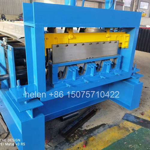
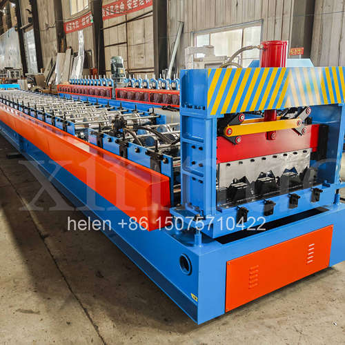
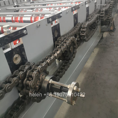
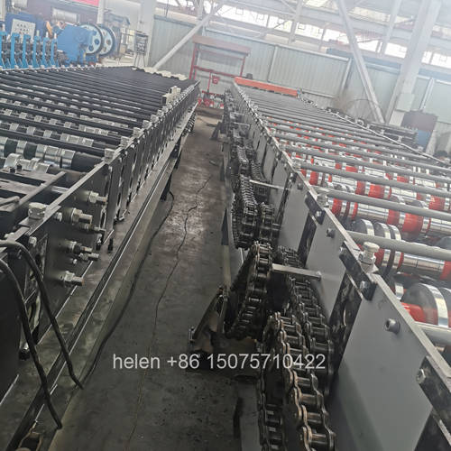
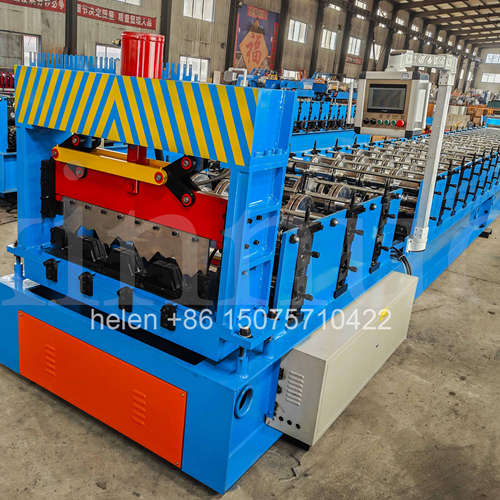
- Heavy structure deck means thicker gauge and higher strength steel
- Forming load rises steeply with thickness and with yield strength
- Springback increases, so sections need more sizing passes
- Frames, shafts, chains and motors all step up a tier
- Corner thinning and edge cracking become real risks
- Shear force at heavy gauge dictates blade design and cylinder count
- Thickness limits are section-specific, not general
Not all metal deck is thin. A large part of the deck produced worldwide sits at the lighter end of the range, where the base sheet is a few tenths of a millimetre thick and the machine's task is to shape material without distorting or marking it. Heavy structure deck is the opposite problem. Material is thicker, often higher in yield strength, sometimes formed into deeper ribs, and the machine has to apply substantially greater force while holding the section to the same dimensional tolerance.
That shift has consequences throughout the machine. The forming load rises much faster than the thickness itself, because both the material volume being deformed and its resistance to deformation increase together. Springback grows, so a section that is correctly formed in the rollers relaxes out of tolerance when it leaves them. Corners thin and can crack. Drive torque and feed force requirements step up, which changes the chain, the motor and the frame. This page sets out what makes deck work heavy, how heavy material changes the forming process, what changes in the machine, where the thickness and grade limits actually lie, how shearing behaves at heavy gauge, what the sections are used for, and how heavy sections should be verified.
| Characteristic | Light or Standard Deck | Heavy Structure Deck | Machine Consequence |
|---|---|---|---|
| Material thickness | Commonly 0.8 – 1.5 mm | Above 1.5 mm, extending well beyond the standard range | The single largest driver of the configuration. Forming load scales steeply with thickness. |
| Yield strength | Standard structural grades | Higher-strength grades for the required capacity at reduced thickness | Higher yield increases forming load and springback independently of thickness, so the two effects compound. |
| Rib depth | Moderate to deep ribs | Deep ribs carrying heavy construction and permanent loading | Deeper forming over thicker material requires the longest trains and the largest wheels. |
| Comment on the process | Forming is a shaping operation | Forming is a high-force operation on a material that resists being shaped | Everything downstream of the forming load — frame, shaft, bearings, chain, motor — is affected. |
| Application | General commercial and industrial floors | Heavy industrial floors, plant platforms, structures carrying substantial concentrated loads | Section accuracy has a direct structural consequence, and verification requirements are correspondingly tighter. |
| Effect | Mechanism | What It Demands of the Machine |
|---|---|---|
| Forming load rises steeply | Both the volume of material being deformed and its resistance to deformation increase, so the load grows much faster than the thickness figure alone suggests | A frame that holds the roll gap under that load, a shaft that does not deflect, a chain that transmits the torque, and a motor that provides it |
| Springback increases | Thicker and stronger material recovers more of its deformation when the forming pressure is released, particularly at relatively generous bend radii | Additional sizing passes and tooling designed with the recovery allowance built in rather than corrected afterwards |
| Corner thinning and cracking | Forming a bend in thick material stretches the outer fibre, and where the corner radius is tight relative to thickness the material thins or tears | More forming steps with smaller increments, and a section design in which the radius is compatible with the thickness |
| Roller pressure and surface marking | Higher contact forces are applied across the roll face, increasing the tendency to mark or burnish the surface | Correct roller finish and hardness, and pressure that is distributed across the roll face rather than concentrated |
| Drive torque and feed force | The total work done per metre of material rises, and the material resists being pulled through the train | A heavier chain, a higher motor rating, and gear drives positioned where the resistance is greatest |
| Thermal effects | Deformation energy appears as heat, which is more noticeable when forming thick material continuously | Attention to lubrication and to the temperature of the machine and the material, particularly at start-up |
| Noise and vibration | Higher forces and heavier moving components produce greater noise and vibration, which affects both the machine and the working environment | A heavier frame, which reduces vibration, and attention to noise levels at the operating position |
| Material variation matters more | A thickness or yield variation that would be immaterial on light gauge can push a heavy-gauge machine into overload | Thickness range established at order, and incoming coil checked rather than assumed |
| Element | Standard Deck Machine | Heavy Duty Deck Machine |
|---|---|---|
| Frame | 400H – 450H depending on the profile and gauge | 450H heavy construction, with flange thickness at the upper end of the range, since frame rigidity is what holds the roll gap |
| Mid plate | 18 – 20 mm | 20 – 25 mm, carrying the higher drive torque and the greater bending moment in the frame |
| Shaft | Φ90 – 95 mm | Φ105 – 115 mm, sized so that deflection under heavy forming load does not open the gap at the point of maximum force |
| Bearings | Standard duty, dual-row self-aligning | Heavier duty bearings, with the rear rows carried on bearing-mounted oversized wheels to control the load path |
| Forming rows | 18 – 28 rows for mainstream profiles | Up to 36 rows, since heavy material and deep ribs require more incremental forming steps |
| Chain | 2 inch external roller chain | 2.5 inch chain, because the torque required to form heavy gauge exceeds what the standard chain transmits reliably |
| Motor configuration | 2 × 11 kW to 2 × 15 kW | 2 × 22 kW or above, with dual motors providing balanced torque along a long heavy train |
| Reinforcement provision | Reinforcement bars at the critical rows | The same provision becomes essential rather than beneficial, since without it the shaft deflects and the section is under-formed |
| Gear drives | Fitted at high-resistance positions | Higher duty at the same positions, because feed force at heavy gauge is the limiting factor for throughput |
| Shear | Dual-cylinder hydraulic shear at floor level | The same arrangement with greater cylinder force and a heavier blade, sized to the cutting load at maximum thickness |
| Blades | Alloy tool steel at HRC 60 – 62 | The same hardness specification with greater blade section, and clearance checked at every material change because heavy gauge is far less forgiving of incorrect clearance |
| Lubrication | Standard schedule | More demanding, because higher contact pressures and temperatures accelerate lubricant breakdown |
| Handling | Panels handled by two people or a trolley | Panels at heavy gauge are heavy in absolute terms, so handling, stacking and lifting provision must be designed rather than assumed |
| Limiting Factor | Consideration | How It Is Established |
|---|---|---|
| Section geometry | The maximum thickness a given section can be formed from depends on its own rib depth, corner radii and flank angles, not on a general figure | Confirmed against the section drawing, since a radius that is generous for one thickness is tight for another |
| Corner radius to thickness ratio | Where the radius is small relative to thickness, the outer fibre is stretched excessively and the material thins or cracks at the bend | Assessed at the tooling design stage, with the radius-to-thickness relationship being the governing geometric criterion |
| Material yield strength | Higher strength increases both forming load and springback, so a given section may be formable in a standard grade and not in a high-strength one at the same thickness | Established from the material specification, with the yield strength stated at the order stage rather than assumed from the grade name |
| Material ductility | Ductility determines how much deformation the material accepts at a corner before cracking | Established from the material certificate and confirmed in the test run on the actual coil to be used |
| Coating | Heavy coatings can crack or flake at tight bends, and a damaged coating at a corner is a corrosion initiation point | Checked on the formed sample, since a coating that survives a light-gauge bend may not survive a heavy-gauge one |
| Machine capability | The heaviest thickness the configuration can form reliably at production speed, as distinct from the heaviest it can form at all | Demonstrated in a test run at the upper end of the ordered thickness range, not at a convenient mid-range gauge |
| The practical rule | Heavy gauge is a system question — section, grade, thickness and machine must be compatible together | Assessed as one package before tooling is produced, since changing any one element afterwards means new tooling or a new machine |
| Consideration | Detail |
|---|---|
| Cutting force | Force rises with thickness and with the strength of the material. At heavy gauge the shear is a high-force operation, which is why a dual-cylinder arrangement is used — two cylinders apply force at two points and keep the blade line balanced across a wide panel. |
| Force balance | A single cylinder on heavy gauge tends to cut unevenly across the section, overloading one end of the blade. Balanced force is what produces consistent ends and protects the blade. |
| Blade section | Blades at heavy gauge carry greater load per cut, so blade section and support must be adequate. Blade hardness remains in the HRC 60 – 62 range, but the load it carries is considerably higher. |
| Blade clearance | Clearance is set for a material thickness. It must be checked at every material change, because incorrect clearance on heavy gauge produces burring, edge cracking and rapid blade wear rather than a merely untidy cut. |
| Cut edge quality | The cut end on heavy gauge is a substantial edge. A burred edge obstructs the lap between panels and is a handling hazard, so edge condition is a functional requirement. |
| Blade life and rotation | Heavy gauge consumes blade life faster. A spare set held on site allows the worn set to be reground while production continues on the spare. |
| Trim waste | Three-blade shearing gives the cleanest edge with approximately 10 mm of trim per cut; two-blade gives no waste with a negligible corner deformation. At heavy gauge the material cost per cut is higher, which strengthens the case for two-blade where the edge condition permits it. |
| Discharge | Floor-level shearing lets heavy panels discharge to the stacking position by gravity, removing manual handling of the heaviest product on the line. |
| Application | Why Heavy Gauge Is Used |
|---|---|
| Heavy industrial floors | Concentrated plant loads and dynamic loading require a section that carries more than a general commercial floor. |
| Plant platforms and equipment floors | Equipment loads, access requirements and the need for stiffness underfoot suit a heavier section. |
| Long spans without intermediate support | Thicker material combined with rib depth provides stiffness where supports cannot be placed. |
| Construction loading domination | Where the wet concrete and construction loading governs the design rather than the finished service load, thicker material provides the construction-stage capacity. |
| Floors with cut-outs and penetrations | Openings reduce local stiffness, and heavier material tolerates the interruption better. |
| Corrosive or demanding environments | Heavier material with a suitable coating provides a longer service life where the environment is aggressive. |
| Where deflection governs | Where the deflection limit rather than strength sets the design, additional thickness is often the most direct solution. |
| Check | Requirement |
|---|---|
| Test run at maximum thickness | At the upper end of the ordered thickness range, since a run at nominal thickness does not demonstrate the capability being purchased. |
| Material of the specified grade | Tested using the grade and yield strength that production will use. Forming a standard grade proves nothing about forming a high-strength one. |
| Corner condition | Inspected for thinning and cracking at every formed corner, since this is where heavy gauge fails first. |
| Springback measurement | Section dimensions measured after the panel has settled, not only immediately after forming. |
| Section dimensions | Cover width, rib height, rib pitch, flank angles and flat widths measured against the drawing at multiple positions. |
| Surface condition | Inspected for marking or burnishing, since higher contact pressures increase the risk. |
| Cut edge | Examined at both ends of several panels, with blade clearance confirmed for the gauge being cut. |
| Machine behaviour under sustained load | Observed over a continuous run rather than a short sample, because load builds and lubricant conditions change over time. |
| Noise and vibration | Assessed at the operating position, since heavier forming produces greater noise and vibration than light-gauge work. |
| Information | Why It Determines the Specification |
|---|---|
| Section drawing | The authoritative input. Rib depth, corner radii, flank angles and pitch determine whether the section is formable at the required thickness. |
| Maximum material thickness | The governing figure for the configuration tier, the drive and the shear. The maximum matters, not the average. |
| Material grade and yield strength | Yield strength affects forming load and springback independently of thickness, so it should be stated explicitly. |
| Material ductility and certificate | Determines how much deformation the material accepts at a corner before cracking. |
| Coating system and thickness | Affects bend performance and the surface protection requirements through the forming train. |
| Effective cover width and blank width | Sets roller and shaft length, the decoiler working width and what coil must be purchased. |
| Required production rate at maximum gauge | Determines the drive rating and whether the configuration must move to the heaviest tier. |
| Panel length range | Drives run-out provision, cut length control and handling arrangements for panels that are heavy as well as long. |
| Shear preference | Three-blade or two-blade, which at heavy gauge has a materially larger material cost implication than at light gauge. |
| Lifting and handling provision available | Heavy panels cannot be handled by hand, so site provision affects the specification and the layout. |
| Parameter | Standard Range |
|---|---|
| Profile type | Structural deck sections produced to the buyer's drawing for heavy structure applications |
| Material thickness | Above 1.5 mm, extending to the heaviest gauge the section geometry and grade will accept; the maximum is confirmed section by section |
| Material grade | Standard and higher-strength structural grades, with yield strength stated explicitly at order |
| Material | Galvanized, aluminium-zinc coated and pre-painted coil, with coating bend performance verified on the formed sample |
| Forming rows | Up to 36 rows, since heavy gauge and deep ribs require more incremental forming steps |
| Frame | 450H heavy welded H-section with flange thickness at the upper end of the range |
| Mid plate | 20 – 25 mm |
| Shaft | Φ105 – 115 mm round bar, rough turned then precision ground |
| Bearing provision | Heavy duty bearings with bearing-mounted oversized wheels across the rear forming rows |
| Forming wheels | 45# forged steel, quenched to HRC 45 – 50, finish turned, keyed, polished and chrome plated |
| Reinforcement provision | Reinforcement bars at the embossing row, main drive, rib-forming rows and sizing rows |
| Gear drives | Fitted at the embossing row, ahead of the bearing-mounted wheel section, and at the exit rows |
| Transmission | 2.5 inch external roller chain |
| Motor configuration | 2 × 22 kW or above, with variable frequency drive and overload and thermal protection |
| Shear | Dual-cylinder hydraulic shear at floor level, sized to the cutting force at maximum thickness, with balanced force across the panel width |
| Blades | Alloy tool steel at HRC 60 – 62 with adequate section for the load, spare set supplied, clearance checked at every material change |
| Blade options | Three-blade for the cleanest edge with approximately 10 mm trim waste, or two-blade for zero waste with negligible edge deformation |
| Forming speed | Set by section depth, thickness and grade; the rate that holds the section, not the highest available |
| Cut length tolerance | ±1.5 mm |
| Lubrication | Schedule and lubricant grade suited to higher contact pressures and temperatures |
| Handling | Run-out, stacking and lifting provision designed for panels that are heavy as well as long |
| Control system | PLC with colour touchscreen HMI, sheet count control, overload indication and stored recipe banks |
| Electrical supply | 380 V / 50 Hz / 3-phase standard, with supply capacity sized to the higher motor rating; alternative voltages by destination |
| Certification | CE marking and ISO 9001:2015 compliant manufacturing, with destination-market documentation arranged as required |
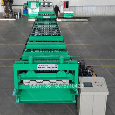
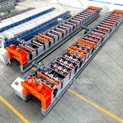
Coil loading on the decoiler, strip entry through the guide, progressive forming across a long roll train where the load is shared across reinforcement bars, bearing-mounted rear wheels and gear drives, sizing over the final passes, length measurement, dual-cylinder cutting at floor level, and gravity discharge to the stacking position follow the established sequence, with the configuration sized to the maximum thickness and yield strength the section is expected to be produced from.
Hebei Xinnuo is a professional cold roll forming machinery manufacturer with 20+ years of experience. We specialize in C/Z purlin machines, roof panel roll formers, floor deck machines, and custom profile solutions — exported to 50+ countries worldwide.