helen@hbxinnuorollforming.com
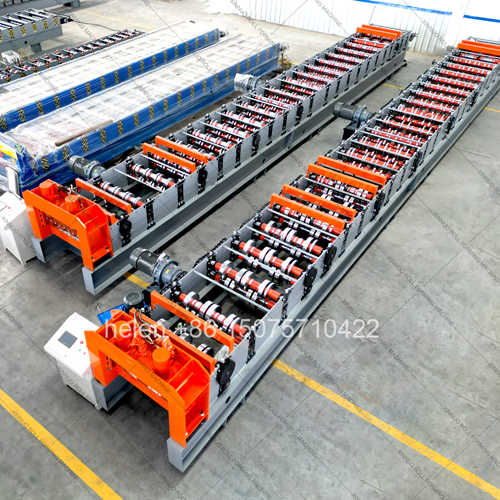
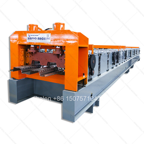
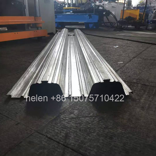
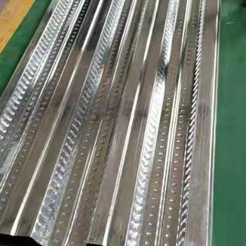
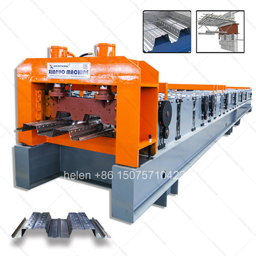
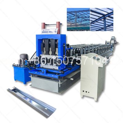
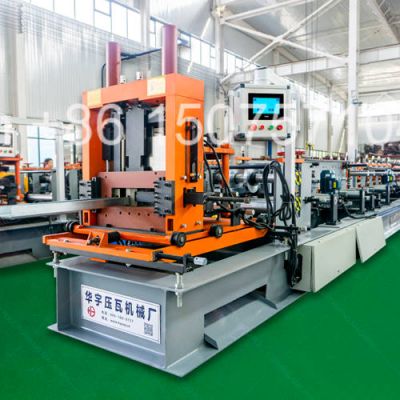
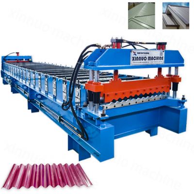
- Heavy-duty floor deck roll forming machine for structural steel decking production
- Dual 11KW motor drive system for 0.8–1.5mm thick galvanized steel processing
- Five anti-pooling mechanisms prevent material jamming in deep rib forming
- Produces open and closed deck profiles with concrete embossment dimple wheels
- 400H heavy structural frame with Φ90–115mm shafts for decades of operation
- Dual-cylinder floor-standing hydraulic shear with gravity-assisted panel stacking
Floor deck roll forming machines are fundamentally different from standard roof panel roll formers. While roof panel machines shape thin-gauge steel (0.3–0.8mm) into shallow profiles (15–40mm rib height), floor deck machines must cold-form thick structural steel (0.8–1.5mm) into deep rib profiles (50–153mm) that serve as permanent concrete formwork and tensile reinforcement in multi-story steel-frame buildings. The forming forces are 3–5 times greater, requiring purpose-built heavy-duty engineering at every component level.
| Component | Floor Deck Machine | Standard Roof Panel Machine |
|---|---|---|
| Material Thickness | 0.8 – 1.5 mm galvanized structural steel | 0.3 – 0.8 mm color-coated steel |
| Rib Height | 50 – 153 mm deep trapezoidal or dovetail | 15 – 40 mm shallow wave or trapezoidal |
| Forming Stations | 22 – 36 rows (gradual deep-draw shaping) | 14 – 18 rows |
| Frame Construction | 400H – 450H Laisteel beam, 10mm wing, 18–25mm mid-plate | 300H beam, 12–14mm mid-plate |
| Shaft Diameter | Φ90 – 115 mm, 100mm round bar, chrome plated | Φ70 – 80 mm |
| Drive Power | 2 × 11 KW dual motors (up to 2 × 15 KW) | 1 × 3 – 5.5 KW single motor |
| Chain Drive | 2-inch external chain (up to 2.5-inch heavy duty) | 6-fen or 1-inch chain |
| Shear System | Dual-cylinder floor-standing hydraulic shear | Single-cylinder post-cut shear |
| Anti-Pooling Devices | 5 mechanisms — clutch, bearing wheels, pressure bars, gears, dual-cylinder shear | Not required |
| Output Function | Structural formwork + tensile reinforcement + composite floor slab | Weather enclosure only |
| Profile Model | Effective Width | Rib Height | Peaks (Ribs) | Deck Type | Typical Application |
|---|---|---|---|---|---|
| 688 Type | 688 mm | 76 mm | 2 ribs | Open deck | Standard commercial floors, 2–3m spans |
| 720 / 750 Type | 720 – 750 mm | 51 – 53 mm | 3 ribs | Open deck | Residential and light commercial floors |
| 780 Type | 780 mm | 50 mm | 3 ribs | Open deck | Mid-span industrial flooring |
| 820 Type | 820 mm | — | 3 ribs | Closed deck (闭口) | Long-span floors above 3m, parking structures |
| 870 Type | 870 mm | 60 mm | 3 ribs | Open deck | Medium commercial construction |
| 915 Type | 915 mm | 75 – 76 mm | 3 ribs | Open deck | Heavy commercial and industrial floors |
| 1000 / 1025 Type | 1000 – 1025 mm | 50 – 51 mm | 3 ribs | Open deck | Wide-span steel structure buildings |
Material pooling (淤板) is the single most common failure mode in floor deck roll forming. As the deep rib profile is progressively shaped, friction forces build exponentially. Standard roof panel machines have no defense against this — but floor deck machines require purpose-designed anti-jamming systems at critical forming points.
| Parameter | Standard Configuration | Heavy-Duty Configuration |
|---|---|---|
| Compatible Profiles | 688 / 750 / 915 / 1000 / 1025 mm | Plus 820 closed deck, 870, custom widths |
| Material Thickness | 0.8 – 1.2 mm galvanized steel | 0.8 – 1.5 mm galvanized steel |
| Material Yield Strength | G250 – G350 | G350 – G550 high-strength |
| Feed Coil Width | 1000 – 1250 mm | Up to 1500 mm |
| Forming Stations | 22 – 27 rows | 28 – 36 rows |
| Dimple Wheel | 45# forged steel, HRC 45–50, polished, chromed | Same, with quick-change keyway |
| Frame | 400H Laisteel, 10mm wing, 18mm mid-plate | 450H Laisteel, 10mm wing, 25mm mid-plate |
| Shaft Material | Φ90 – 100 mm round bar, chrome plated | Φ100 – 115 mm round bar, chrome plated |
| Main Drive | 2 × 11 KW (2 × 8# 11KW) dual motors | 2 × 15 KW (2 × 6# 15KW) dual motors |
| Chain | 2-inch external chain drive | 2.5-inch external chain drive |
| Anti-Pooling | 5 mechanisms — clutch, bearing wheels, pressure bars, gear drives, dual-cylinder shear | Same, with enhanced gear drive ratios |
| Shear System | Dual-cylinder hydraulic floor-standing, gravity discharge | Same, with servo length control option |
| Cutting Method | Hydraulic post-cut shear | Hydraulic post-cut with encoder feedback |
| Production Speed | 8 – 12 m/min | 8 – 15 m/min |
| Control System | PLC + touchscreen HMI, length and batch control | PLC + touchscreen HMI with production logging |
| Decoiler | 5-ton hydraulic, manual expansion | 7-ton hydraulic, powered expansion |
| Total Line Length | Approx. 22,000 mm (22 m) | Approx. 25,000 mm |
| Forming Unit Dimensions | 14,500 × 2,750 mm | 16,000 × 3,000 mm |
| Total Power | 25 – 30 kW | 35 – 45 kW |
| Feature | Open Floor Deck (开口楼承板) | Closed Floor Deck (闭口楼承板) |
|---|---|---|
| Profile Shape | Trapezoidal ribs with open top | Re-entrant dovetail shape with narrow top opening |
| Concrete Bonding | Relies on embossments (dimples) on rib sides and top | Concrete wraps around dovetail ribs, mechanical interlock |
| Machine Complexity | Standard 22–27 row forming | 36-row forming with special locking roller set |
| Span Capability | Up to 3 meters without temporary propping | Above 3 meters with fewer or no props |
| Shear Stud Requirement | Required for composite action | Reduced or eliminated — dovetail geometry provides interlock |
| Typical Projects | Standard commercial, residential, industrial floors | High-rise composite floors, elevated parking, long-span structures |
| Market Demand | Higher volume, price-sensitive | Growing demand, premium pricing |
| Line Section | Equipment | Dimensions / Notes |
|---|---|---|
| Decoiler Station | A-frame hydraulic decoiler with coil car | 1,450 mm wide × 6,500 mm tall (coil loading height) |
| Entry Guide | Material straightening and centering device | Ensures strip alignment before entering first forming row |
| Forming Main Unit | 22–36 station roller cascade with anti-pooling devices | 14,500 mm long × 2,750 mm wide (machine body only) |
| Dimple Wheel Station | Embossment roller with clutch mechanism | Presses concrete-gripping dimples into rib surfaces |
| Post-Form Sizing | Bearing-mounted oversized wheels + gear drive | Final profile calibration, 10-row push-through section |
| Cutting Section | Dual-cylinder floor-standing hydraulic shear | Panel drops by gravity to stacking area after cut |
| Run-Out Table | Roller conveyor with panel collection rack | 3,000 mm long, gravity-assisted stacking |
| Control Cabinet | PLC + touchscreen, motor control, emergency stops | 3,000 mm floor space, positioned left side |
| Total Floor Space Required | — | 25 m × 8 m minimum (including coil loading and panel stacking zones) |
| Stage | Operation | Machine Section |
|---|---|---|
| 1. Coil Loading | Galvanized steel coil (0.8–1.5mm) loaded onto A-frame hydraulic decoiler; strip fed through straightening guides | 5-ton hydraulic decoiler with powered expansion |
| 2. Progressive Forming | Steel strip passes through 22–36 roller stations; deep trapezoidal ribs formed incrementally to 50–153mm height | Multi-station roller cascade with gear drives |
| 3. Dimple Embossing | Embossment roller presses concrete-gripping dimples into rib surfaces; clutch disengages drive after pass-through | Dimple wheel station with clutch mechanism |
| 4. Sizing and Calibration | Final 10 rows with bearing-mounted oversized wheels and pressure bars ensure precise profile geometry | Push-through sizing section with anti-pooling devices |
| 5. Length Cutting | Dual-cylinder floor-standing shear cuts panel at programmed length; panel drops by gravity onto stacking table | Hydraulic post-cut shear, encoder length control |
| 6. Panel Collection | Finished floor deck panels stacked and bundled for transport to construction site | Gravity-assisted roller conveyor and stacking rack |
The dual-motor drive system ensures balanced torque distribution across the entire forming train, eliminating the power loss and uneven speed issues common in single-motor designs. The five anti-pooling mechanisms work together to prevent material jamming through the deep-draw forming sequence, enabling consistent production at 8–12 meters per minute with 0.8–1.5mm thick structural grade steel.
Hebei Xinnuo is a professional cold roll forming machinery manufacturer with 20+ years of experience. We specialize in C/Z purlin machines, roof panel roll formers, floor deck machines, and custom profile solutions — exported to 50+ countries worldwide.