helen@hbxinnuorollforming.com
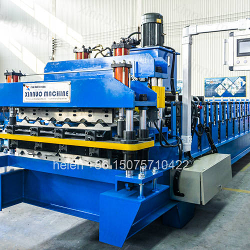
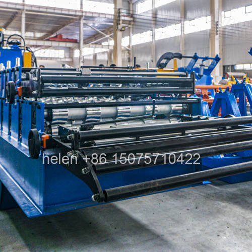
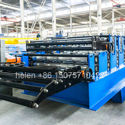
- Site readiness, foundation and power checks precede any machine positioning
- Frame levelling and squareness establish the reference for both decks
- The glazed tile deck needs pitch calibration and is hardest to commission
- Roof sheet deck alignment is verified first, then tile deck geometry
- Most profile defects trace to roller gap, alignment, or material variation
- Commissioning runs two days for the sheet deck, longer for tile
- Fault diagnosis follows a defined sequence before any roller is adjusted
A double layer glazed tile and roof sheet roll forming machine is judged in practice not by its specification sheet but by whether it produces saleable sheets reliably from the first week of operation. That outcome is determined less by the machine itself than by three things that happen after it arrives: how carefully the site was prepared, how methodically the two decks were commissioned, and how systematically the operator diagnoses a fault when sheet quality drifts. Two identical machines installed to different standards will perform differently for years, and the difference is almost entirely attributable to these three activities.
This page sets out the installation and commissioning sequence for a two-deck machine, with particular attention to the glazed tile deck, which is the more demanding of the two because it combines continuous roller forming with an intermittent pitch-stamping operation that must be synchronised to the line. It then provides a fault diagnosis matrix that traces common sheet defects back to their actual causes, so that problems are corrected at source rather than by adjusting rollers at random.
| Readiness Item | Requirement | Consequence If Incomplete at Arrival |
|---|---|---|
| Foundation complete and cured | Reinforced concrete pad of specified thickness and grade, cured for the full period before loading | Machine cannot be positioned without risk of the pad deforming under load, which permanently disturbs frame levelling |
| Anchor positions verified | Bolt positions match the foundation drawing supplied with the machine | Site drilling of cured concrete is required, weakening the pad and delaying installation |
| Pad level within tolerance | Level across the full machine footprint before any load is applied | Excessive shimming is required under the frame, which reduces the rigidity that the frame was designed to provide |
| Electrical supply terminated | Supply of the correct voltage, frequency, and phase, with an isolator within reach of the control panel | Commissioning cannot begin, and temporary connections are made that often persist far longer than intended |
| Lifting equipment arranged | Crane or forklift of sufficient capacity on site at the scheduled unloading time | The frame sits in the yard or on the truck, exposed to weather and to accidental damage |
| Trial coil available | Coil in the widths and gauges required by both decks, in sufficient quantity to align and prove each | Commissioning stalls partway through, and the decks are left in an unproven condition |
| Access route clear | Route from the unloading point to the installation bay can accommodate the largest frame section | Sectional disassembly is required to move the machine in, adding cost and introducing alignment risk |
| Operating staff identified | The personnel who will run the machine are present during commissioning, not merely informed afterwards | Knowledge stays with the commissioning technician and leaves with them |
| # | Stage | Typical Duration | Key Point |
|---|---|---|---|
| 1 | Unpacking and inventory | Half day | Check every item against the packing list and record any transit damage photographically before signing receipt |
| 2 | Removal of transit protection | Half day | Remove anti-corrosion coating from machined surfaces; do not leave it in place and begin forming with it present |
| 3 | Positioning main frame | Half to one day | Set the frame on the anchor positions without final tightening, allowing adjustment during levelling |
| 4 | Frame levelling and squareness | Half day | This is the most important stage in the whole installation; every subsequent measurement depends on it |
| 5 | Anchor tightening and grouting | Half day | Tighten progressively and in sequence; re-check level afterwards as tightening can disturb what levelling established |
| 6 | Decoiler installation | Half day | Align the decoiler centre line with the machine entry so that the strip enters straight and unstressed |
| 7 | Hydraulic power pack installation | Half day | Fill with the specified oil grade, check for leaks before pressurising, and confirm cooler airflow is unobstructed |
| 8 | Control cabinet and wiring | One day | Verify supply voltage and phase rotation before energising, and confirm earthing before any powered test |
| 9 | Run-out table installation | Half day | Set level and square to the machine exit so sheets discharge without rubbing or skewing |
| 10 | Dry run without material | Half day | Run both decks unloaded to confirm chain tracking, clutch engagement at each position, and absence of abnormal noise |
| Measurement | Target Tolerance | What It Protects |
|---|---|---|
| Frame level along its length | Within approximately 0.1 mm per metre | Prevents the material from climbing or dipping as it travels through the forming line, which distorts rib height along the sheet |
| Frame level across its width | Within approximately 0.1 mm per metre | Prevents roller gap from varying side to side, which produces a sheet that curls or measures unevenly across its width |
| Diagonal squareness | Diagonal difference within approximately 1 mm | Confirms the frame is not twisted, which would skew the strip as it enters and cause it to track toward one side |
| Shaft parallelism within each deck | Within approximately 0.03 mm per 100 mm | Keeps the material travelling perpendicular to the roller axes rather than being drawn to one side |
| Roller gap uniformity across width | Variation within approximately 0.02 mm | Directly determines whether rib or wave geometry is consistent from one edge of the sheet to the other |
| Deck-to-deck reference alignment | Consistent with the frame reference established in stage 4 | Ensures that correcting one deck does not disturb the geometry of the other, which is the specific risk in stacked architecture |
| Commissioning Stage | Roof Sheet Deck | Glazed Tile Deck |
|---|---|---|
| Order of work | Commissioned first, because it establishes the material path and the operating pattern | Commissioned second, once the sheet deck is proven and the operator understands the line |
| First material pass | Low speed only, with the operator watching both sheet edges for tracking | Low speed, with the stamping mechanism initially disengaged so the base profile forms cleanly |
| Profile verification | Rib height, pitch, effective width, and straightness measured against the profile drawing | Base profile geometry verified before the stamping mechanism is brought into operation |
| Cutting setup | Length parameters entered and verified against measured sheet length at two or three settings | Same length verification, repeated because the tile deck runs at a different effective speed |
| Secondary stage | Speed raised progressively to normal operating level with dimensional checks repeated | Stamping mechanism engaged and pitch distance set, then verified over a full sheet length |
| Typical duration | Approximately one to one and a half days | Approximately two to three and a half days, reflecting the additional calibration |
| Main difficulty | Relatively low; continuous forming with no intermittent operation to synchronise | Higher; the pitch-stamping operation must be timed correctly against material position, and pattern geometry must be held consistently |
| # | Calibration Step | Purpose and What to Watch For |
|---|---|---|
| 1 | Confirm base profile stability | The tile base profile must be dimensionally consistent before the stamping mechanism is engaged, otherwise stamping faults will be attributed to the die when the base profile is at fault |
| 2 | Set pitch distance on the controller | For servo-driven stamping, enter the pitch distance directly. For cam-driven stamping, confirm the cam fitted corresponds to the required pitch. |
| 3 | Verify stamping timing | The press must fall only on material that has completed its forming passes. Early timing distorts the base profile at the step; late timing produces an incomplete step. |
| 4 | Run a full sheet length | Pitch error accumulates along the sheet, so calibration must be verified over the longest sheet the machine will produce rather than over a short sample. |
| 5 | Measure pitch repeatability | Measure the distance between several successive steps on the same sheet; variation indicates timing drift or material slip. |
| 6 | Confirm step depth | Insufficient stamping force leaves a shallow step; excessive force marks or thins the material at the step edge. |
| 7 | Check edge condition | The tile step must not produce coating damage at its edges, which is the defect most visible to an end customer on an installed roof. |
| 8 | Record the settings | Record pitch distance, timing, and force settings in the machine log so that they can be restored after a controller fault. |
| Symptom During Commissioning | Likely Cause | Corrective Action |
|---|---|---|
| Strip tracks to one side | Side guides not centred, decoiler misaligned with the machine entry, or frame not square | Re-check decoiler centre line against the machine entry before adjusting any forming roller |
| Sheet curls along its length | Uneven roller gap distribution across the two sides, or a shaft not parallel to its counterpart | Measure gap at both ends of each roller rather than at the centre only |
| Rib or wave height inconsistent | Insufficient forming rows for the profile depth, or roller gap set too wide at the finishing stations | Confirm the row count against specification before altering gap settings; rows cannot be compensated by gap adjustment |
| Coating marked or scratched | Transit coating not fully removed, debris on a roller surface, or a guide contacting the painted face | Inspect every roller working surface under raking light before blaming the material |
| Tile pitch drifts along the sheet | Stamping timing not synchronised, encoder slip, or material slipping in the drive | Verify stamping timing first, then encoder calibration, before changing the die or pitch setting |
| Tile step incomplete or shallow | Insufficient stamping force, die wear, or material thinner than the die was set for | Check material thickness against the setting before increasing force, which can damage the die if the cause lies elsewhere |
| Cut length varies between sheets | Measuring wheel slipping, encoder coupling loose, or material slipping under the shear | Inspect the measuring wheel contact and encoder coupling before altering length parameters |
| Burrs or coating damage at the cut edge | Blade wear, incorrect blade clearance, or blade not square to the material path | Check blade clearance against material gauge before replacing blades |
| Abnormal noise under load | Chain tension incorrect, sprocket misalignment, or a bearing not seated correctly | Stop and investigate immediately; continuing operation with a seating fault accelerates wear on the shaft |
Once the machine is in production, faults appear as sheet defects rather than as commissioning problems. The matrix below works backwards from the visible defect to the underlying cause, in the order in which the causes should be checked.
| Sheet Defect | Check In This Order | Why This Order |
|---|---|---|
| Wavy sheet edges | 1. Material yield strength or thickness change from a new coil 2. Roller gap at finishing stations 3. Shaft bearing seating | Material variation explains most sudden onset defects and costs nothing to check. Roller and bearing faults develop slowly and are less likely to appear overnight. |
| Rib height variation across width | 1. Roller gap measured at both ends 2. Bearing housing seating 3. Shaft straightness | The defect is lateral, so the cause is most likely lateral. Checking gap at both ends identifies the majority of cases immediately. |
| Coating cracking at rib base | 1. Row count against the profile specification 2. Bend radius designed into the tooling 3. Material ductility of the current coil 4. Roller gap | This defect indicates over-deformation. Row count and bend radius are design factors that gap adjustment will not correct. |
| Tile pitch error accumulating | 1. Stamping timing against material position 2. Encoder signal and measuring wheel contact 3. Material slip through the drive | Pitch error is a synchronisation problem, not a die problem. Replacing the die will not resolve it. |
| Scratch lines along the sheet | 1. Debris on the roller surface 2. Transit coating residue 3. Guide contact with the painted face 4. Roller surface condition | Most scratch defects are contamination rather than damage and clear with cleaning. Roller damage is confirmed only after contamination is excluded. |
| Sheet twist | 1. Side guide alignment 2. Frame squareness since installation 3. Drive chain tension balance between decks | Twist develops along the line, so the entry condition is checked before the drive condition. |
| Length inconsistency | 1. Measuring wheel contact pressure 2. Encoder coupling 3. Material slip at the shear 4. Controller length parameter | The controller parameter is last because it rarely changes by itself, whereas mechanical contact does. |
| # | Test | Acceptance Basis |
|---|---|---|
| 1 | Roof sheet deck dimensional test | A continuous run of sheets measured against the profile drawing, covering more than a single sample |
| 2 | Glazed tile deck dimensional test | Base profile and tile step geometry both measured, with pitch repeatability verified along a full sheet |
| 3 | Coating integrity inspection | Formed pre-painted sheets examined under raking light for marking, cracking, and edge damage from both decks |
| 4 | Length accuracy at multiple settings | Sheets cut at three different programmed lengths on each deck and measured against the programmed value |
| 5 | Deck changeover test | Switch between decks at least twice; the first sheet after each change should meet specification without recalibration |
| 6 | Chain tension balance check | Tension verified at each selector position; imbalance indicates a drive configuration that will cause speed divergence |
| 7 | Thermal stability under sustained run | Extended production with bearing and gearbox temperatures monitored to confirm the frame and drive are not overloaded |
| 8 | Controller function verification | Recipe storage and recall confirmed independently on each deck, with fault diagnostics displayed in plain language |
| Period | Focus | What to Record |
|---|---|---|
| Days 1 to 7 | Operator familiarisation with deck selection, parameter entry, and shutdown sequence. Production at moderate speed. | Settings used for each profile, and any sheet defects observed with the conditions under which they appeared |
| Days 8 to 15 | Speed raised toward normal operating level. First routine lubrication cycle carried out. | Chain tension after the first week, which typically changes as components bed in |
| Days 16 to 22 | First roller surface inspection and first blade edge check. Roller gap settings verified as unchanged. | Roller surface condition and blade edge condition as the baseline for future comparison |
| Days 23 to 30 | Consolidation. Production mix broadened across both decks and, where fitted, across tile patterns. | Dimensional measurements across the full range of profiles and gauges produced, establishing the reference standard |
| Parameter | Standard Range |
|---|---|
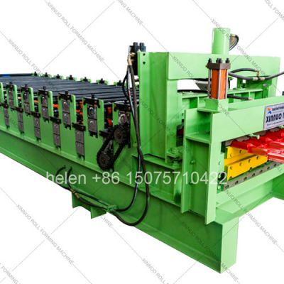
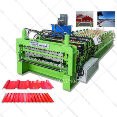
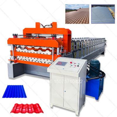
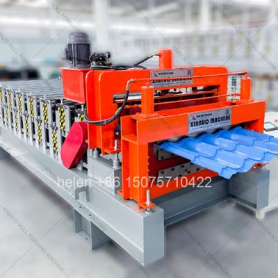
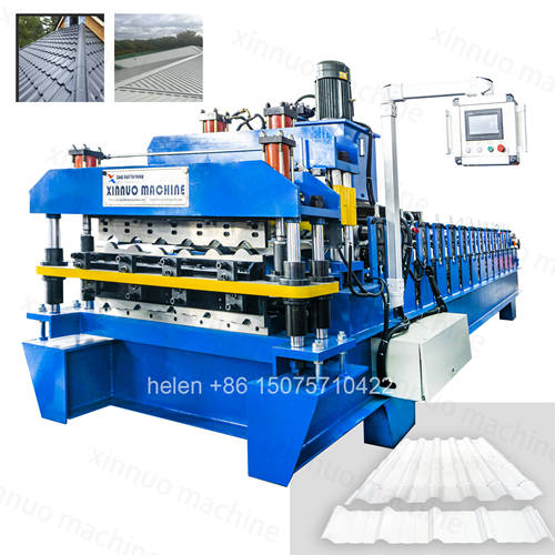
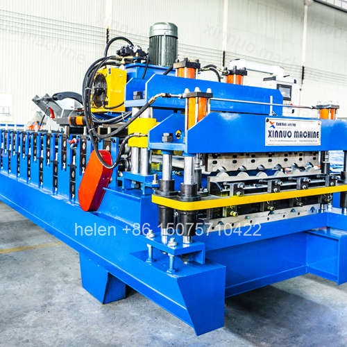
| Machine configuration | Two forming decks stacked vertically in one frame; glazed tile deck with pitch stamping plus roof sheet deck |
| Roof sheet deck profiles | Trapezoidal, corrugated wave, or arc wave, selected against the target market standard |
| Glazed tile deck | Pitch-stamping deck, cam-driven or servo-driven, with pattern-specific stamping die |
| Main frame grade | 300H, 350H, 400H, or 450H welded H-section steel selected against combined deck weight |
| Forming rows per deck | 11 – 18 rows depending on profile family and rib depth |
| Roller material | 45# forged carbon steel, CNC turned, ground, hard chrome plated to HRC 58 – 62 |
| Roller profile tolerance | ±0.03 mm to ±0.05 mm |
| Shaft | Φ75 mm or Φ80 mm solid steel, centerless ground, dual-row self-aligning bearings |
| Transmission | Duplex roller chain with hardened sprockets and selector clutch for deck engagement |
| Main motor | 5.5 kW, 7.5 kW, or 11 kW with variable frequency drive |
| Hydraulic station | 4.0 kW independent power pack with air-cooled oil radiator |
| Forming speed | 8 – 20 m/min; the pitch-stamping deck sets the effective ceiling |
| Material capability | PPGI, PPGL, galvanized, aluminium-zinc coated, pre-painted aluminium; 0.30 – 0.80 mm standard |
| Cutting system | Hydraulic post-cut shear, Cr12MoV blades at HRC 60 – 62 |
| Cut length tolerance | ±1.5 mm |
| Control system | PLC with colour touchscreen HMI and independent recipe banks per deck |
| Installation period | Approximately three to four days from unloading to dry run completion |
| Commissioning period | Approximately two days for the sheet deck; three to four days additional for the tile deck |
| Electrical supply | 380 V / 50 Hz / 3-phase standard; alternative voltages and frequencies by destination |
| Certification | CE marking and ISO 9001:2015 compliant manufacturing |
Coil loading, deck selection at the entry guide, roll forming on the selected deck, glazed tile pitch stamping where that deck is active, length measurement, hydraulic cutting, and discharge to the run-out table follow the established sequence, with deck changeover completed in minutes and no disturbance to either roller set.
Hebei Xinnuo is a professional cold roll forming machinery manufacturer with 20+ years of experience. We specialize in C/Z purlin machines, roof panel roll formers, floor deck machines, and custom profile solutions — exported to 50+ countries worldwide.