helen@hbxinnuorollforming.com
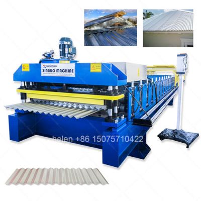
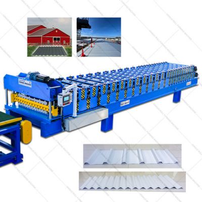
Makes IBR and corrugated steel sheets from flat galvanized coil stock
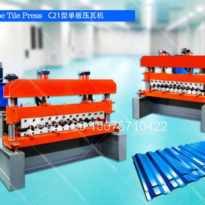
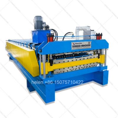
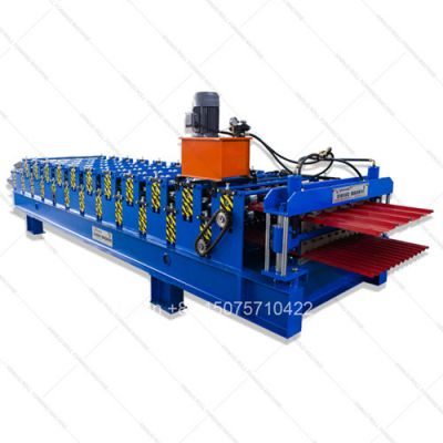
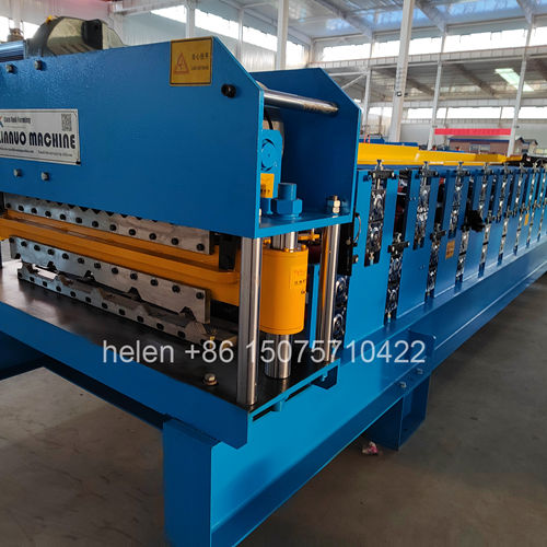
Two independent roller decks mounted vertically on one frame base
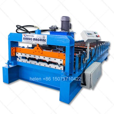
Progressive bending roller stations shape steel into finished sheet profile
PLC digital controller sets sheet length batch count and production speed
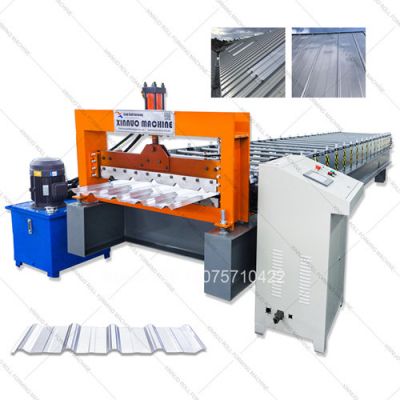
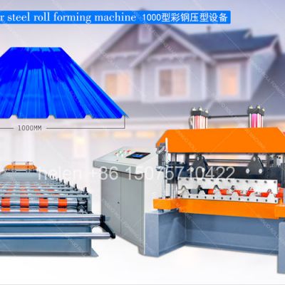
Hydraulic flying shear cuts finished steel sheet without line interruption
Hard chrome roller surfaces prevent zinc coating damage during sheet making
Complete steel sheet production line shipped in single export container
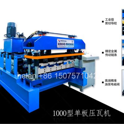
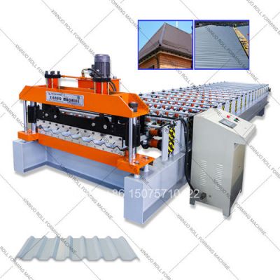
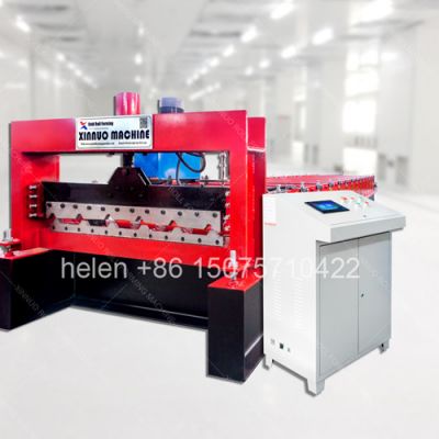
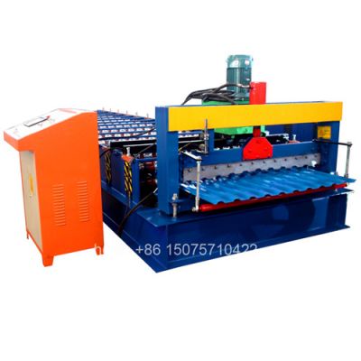
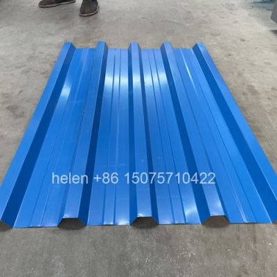
This industrial double layer steel sheet making machine converts flat galvanized or pre-painted steel coil into finished IBR trapezoidal steel sheets and traditional corrugated steel sheets through a precision cold roll forming process. The upper roller deck is configured to make IBR (Inverted Box Rib) steel sheets — structural roof and wall sheeting with deep trapezoidal ribs for industrial and commercial building applications. The lower roller deck makes corrugated steel sheets — the classic sinusoidal wave sheeting that remains the most affordable and widely used metal roofing product in developing markets worldwide. Both steel sheet production capabilities operate from a single machine frame with a shared drive motor, hydraulic cutting system, and PLC automation, allowing manufacturers to make two distinct steel sheet products without doubling their equipment investment.
| Making Stage | Station Position | What Happens to the Steel Strip |
|---|---|---|
| Material Receiving | Station 1 | Flat steel strip arrives from the decoiler under constant brake-controlled tension. The first roller pair receives and guides the strip, establishing the centerline reference axis. Edge constraints begin forming the sheet side flanges as the material enters the making sequence |
| Bend Initiation | Stations 2–5 | Profile-specific roller contours initiate bending at the exact locations where ribs or waves will form. Each station applies a gentle 5–10 degree angular change. The steel remains within safe forming limits, avoiding stress concentrations that could fracture the galvanized zinc coating layer |
| Deep Forming Development | Stations 6–12 | Rib side walls become progressively steeper; valley floor sections flatten under increasing roller pressure; wave curvature radius decreases gradually. The steel undergoes controlled plastic deformation distributed across seven successive stations, producing uniform material flow and consistent sheet thickness throughout all bent regions |
| Final Geometry Setting | Stations 13–16 | The last active forming stations lock in the finished sheet dimensions — rib crest height, valley base width, side wall draft angle, and edge lap detail. Roller profiles incorporate engineered springback allowance so the steel sheet retains its design geometry after passing through the final station |
| Dimensional Verification | Stations 17–18 | A final calibration roller pair acts as a quality assurance station, removing any residual dimensional variation. At this stage the steel sheet has achieved its full engineered cross-section with dimensional accuracy of ±0.5mm across the entire sheet width relative to the profile specification drawing |
| Tooling Specification | IBR Sheet Making Deck | Corrugated Sheet Making Deck |
|---|---|---|
| Forming Station Count | 14–18 pairs of upper and lower making rollers | 13–16 pairs of upper and lower making rollers |
| Roller Steel Grade | 45# medium carbon forged steel billet; ultrasonic tested for internal integrity before machining | 45# medium carbon forged steel billet; ultrasonic tested for internal integrity before machining |
| CNC Profile Making Accuracy | Contour-turned on CNC lathe; profile geometry within ±0.05mm of engineering drawing specification | Contour-turned on CNC lathe; profile geometry within ±0.05mm of engineering drawing specification |
| Hardening Treatment | Controlled-atmosphere gas carburizing furnace; oil quench; surface HRC 58–62; tough ductile core retained for impact resistance | Controlled-atmosphere gas carburizing furnace; oil quench; surface HRC 58–62; tough ductile core retained for impact resistance |
| Surface Plating | Industrial hard chrome electrodeposit; 0.05mm minimum thickness; polished to mirror-grade surface finish for zero material drag | Industrial hard chrome electrodeposit; 0.05mm minimum thickness; polished to mirror-grade surface finish for zero material drag |
| Roller Shaft Specification | Φ75–Φ80mm 40Cr alloy steel; precision ground to h7 tolerance class; keyway machined for drive sprocket mounting | Φ75–Φ80mm 40Cr alloy steel; precision ground to h7 tolerance class; keyway machined for drive sprocket mounting |
| Shaft Bearing Type | Split cast iron pillow block; double-row self-aligning spherical roller bearing; grease lubricated through Zerk fitting | Split cast iron pillow block; double-row self-aligning spherical roller bearing; grease lubricated through Zerk fitting |
| Sheet Product Parameter | IBR Steel Sheet Output | Corrugated Steel Sheet Output |
|---|---|---|
| Finished Sheet Cover Width | 762mm to 1100mm effective coverage | 660mm to 1000mm effective coverage |
| Sheet Profile Depth | 28–43mm rib crown height above valley floor | 12–18mm total wave amplitude crest-to-trough |
| Ribs or Waves per Sheet | 4, 5, or 6 trapezoidal stiffening ribs | 5, 7, 9, or 11 sinusoidal wave undulations |
| Sheet Length Making Range | 1.0m minimum to 14.0m maximum per sheet | 1.0m minimum to 14.0m maximum per sheet |
| Side Joint Design | Single overlap with optional anti-capillary groove for water-tight side lap seal | 1.5-wave minimum side overlap for weatherproof longitudinal sheet joint |
| Flat Coil Input Width | 1000–1250mm before roll forming | 914–1220mm before roll forming |
| System | Engineering Build Specification |
|---|---|
| Welded Machine Frame | Heavy channel steel longitudinal beams cross-braced with H-beam vertical columns (300H–400H structural grade). Complete assembly thermally stress-relieved in industrial furnace after welding to eliminate residual fabrication stress. All bearing mounting pads precision machined post heat-treatment to guarantee exact shaft alignment across every roller station in both sheet making decks |
| Main Drive Motor and Gearbox | 5.5kW or 7.5kW AC induction motor (4-pole, IP54 rated) driving a dual-output worm gear speed reducer with oil-bath lubrication. Reduction ratio 1:40 for higher-speed thin-gauge sheet making or 1:59 for higher-torque thick-gauge processing. Each output shaft independently powers one sheet making deck through separate heavy-duty double-row roller chain circuits with hardened alloy sprockets on every shaft |
| Hydraulic Sheet Cutting Unit | 4.0kW gear pump motor with 80L oil reservoir, inline filtration, breather, and temperature monitoring. Flying shear carriage on linear guide rails with pneumatic sheet clamp. Cr12MoV cold-work die steel blade set, vacuum heat treated to HRC 60–64, profile-ground to match the steel sheet cross-section for clean, burr-free cuts that preserve the sheet profile geometry |
| PLC Digital Control System | Programmable logic controller (Siemens S7-1200, Delta DVP, or Mitsubishi FX3U per customer order), variable frequency drive inverter for stepless sheet making speed control, 7-inch or 10-inch color touchscreen HMI with multi-language operator interface, rotary pulse encoder on the final forming shaft for real-time sheet length measurement, mechanical limit switches for shear carriage home and over-travel position detection, three emergency stop buttons positioned at entry, shear, and exit operator stations along the sheet making line |
| Position | Equipment Unit | Function in Sheet Making Operation |
|---|---|---|
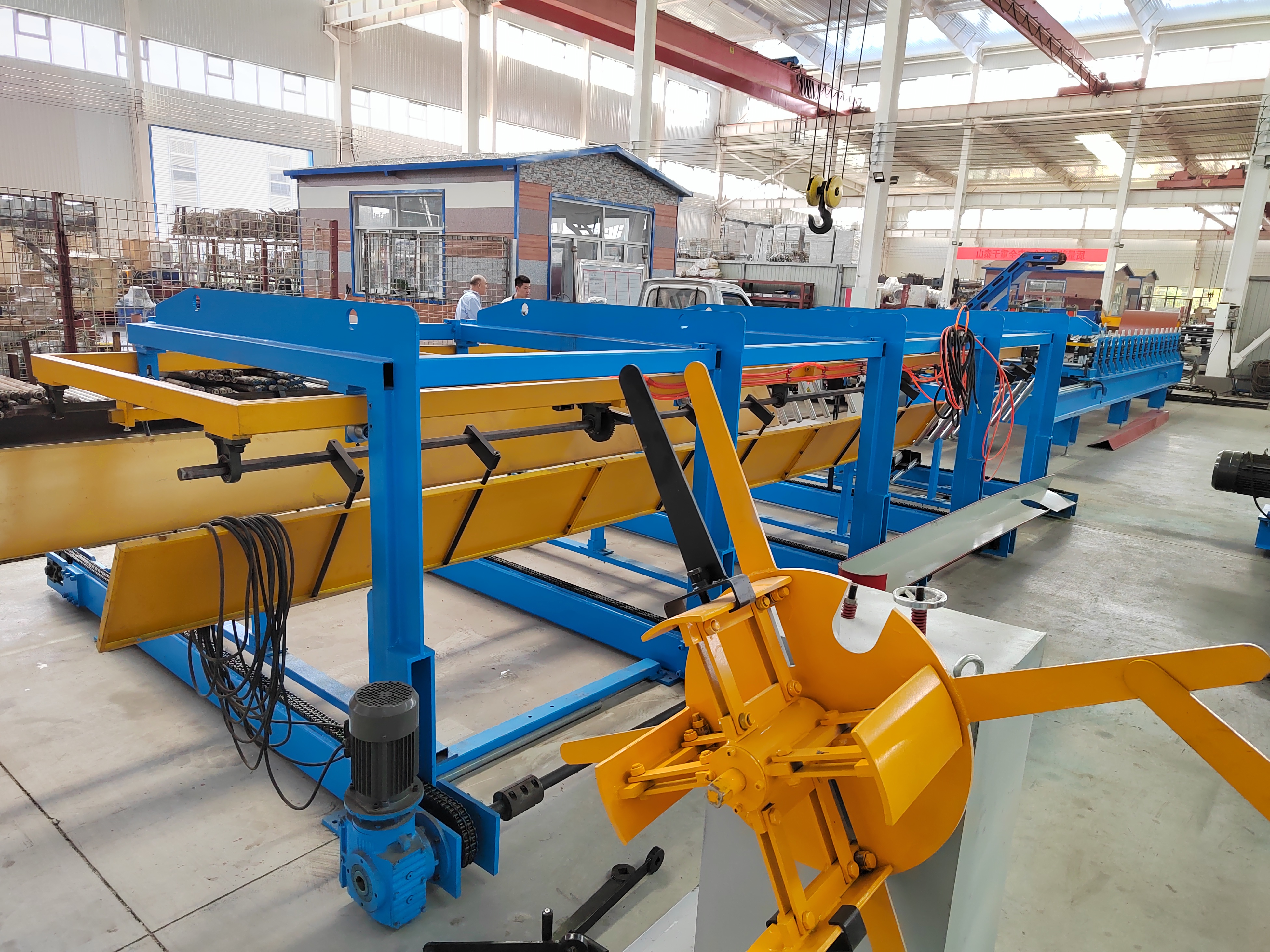
| 1 | Hydraulic Mandrel Decoiler | Holds the steel coil on expanding hydraulic jaws with 5-ton or 8-ton load rating; adjustable disc or pneumatic brake provides controlled strip pay-off tension for uniform sheet making quality throughout each coil |
| 2 | Entry Guide and Pre-Shear Unit | Adjustable-width side guide roller rails center the incoming strip on the making machine axis; integrated manual guillotine blade squares the coil leading edge before threading into the selected roller deck for sheet production |
| 3 | Double Layer Main Making Machine | Central sheet making unit combining the upper IBR roller deck and lower corrugated roller deck on a single welded frame; pivoting diverter plate at the entry selects which deck receives the strip; shared motor drive, gearbox, chain loops, hydraulic shear, and PLC controller serve both decks |
| 4 | Flying Post-Cut Hydraulic Shear | On cut signal the shear carriage accelerates to match line speed; pneumatic clamp grips the formed steel sheet; hydraulic cylinder drives the profiled blade through the sheet cross-section; carriage and blade retract to home position — the complete cut cycle executes without slowing or stopping sheet production |
| 5 | Digital Control Cabinet | IP54 rated steel electrical enclosure containing PLC processor, VFD inverter, motor contactors, overload protectors, circuit breakers, and terminal blocks; external color touchscreen HMI for operator sheet length programming, batch count setting, making speed adjustment, and fault condition display |
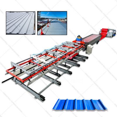
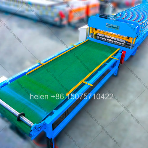
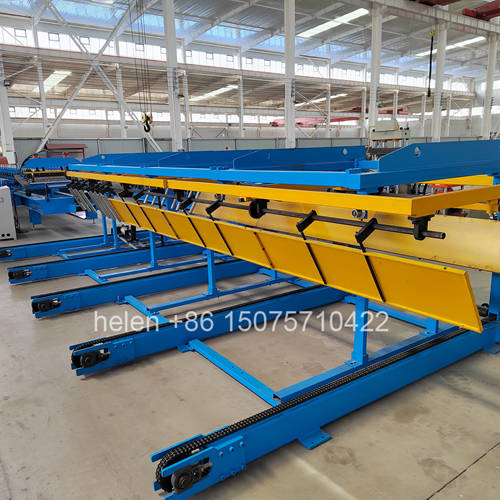
| 6 | Sheet Discharge Conveyor | 3m–5m free-roller receiving table with height-adjustable legs; collects finished cut steel sheets as they exit the shear station and supports them for manual stacking, bundling, and transport to finished goods storage |
| Specification Parameter | Technical Data |
|---|---|
| Compatible Steel Coil Types | Hot-dip galvanized steel coil (zinc coating Z60–Z275 g/m²), pre-painted galvanized iron (PPGI with PE, SMP, or PVDF topcoat), aluzinc/Galvalume (AZ150–AZ200), cold-rolled steel strip, aluminum alloy sheet (1100 and 3003 series) |
| Steel Thickness Making Range | 0.25mm to 0.80mm (equivalent to gauge 30 through gauge 20) |
| Steel Yield Strength Limit | 200 MPa to 400 MPa covering standard mild steel through high-tensile structural steel grades |
| Sheet Making Line Speed | 10–18 linear meters per minute; infinitely variable speed control through VFD inverter interface |
| Sheet Cut Length Accuracy | ±1.0mm at any programmed sheet length via rotary encoder real-time digital pulse feedback to PLC auto-correction algorithm |
| Sheet Type Changeover Method | Manual pivoting material diverter plate repositioning; switch from IBR sheet making to corrugated sheet making in approximately 10–15 minutes including strip re-threading through the alternate deck |
| Electrical Power Requirement | 380V 50Hz 3-phase standard; custom voltage (220V, 415V, 440V, 480V) and frequency (50Hz or 60Hz) configured to match the destination country electrical grid specification |
| Total Installed Motor Power | Approximately 10–12 kW combined (main drive motor 5.5/7.5kW + hydraulic pump motor 4.0kW) |
| Machine Overall Dimensions | Approximately L 7.0–8.0m × W 1.4–1.6m × H 1.7–2.0m; final dimensions determined by ordered roller station count and frame specification grade |
| Machine Net Weight | 5.0 to 7.5 metric tons depending on profile configuration, roller station quantity, and frame structural grade selected |
| Decoiler Coil Capacity | 5 metric tons standard duty or 8 metric tons heavy duty per customer daily production volume requirement |
| Coil Inner Bore Diameter | Φ508mm industry standard; Φ610mm with decoiler mandrel adapter sleeve available upon request |
| No. | Making Step | Operational Detail |
|---|---|---|
| 1 | Coil Setup | Steel coil crane-lifted onto the hydraulic decoiler mandrel; expansion jaws engage and lock the coil inner bore securely; brake resistance adjusted to deliver uniform strip tension throughout the entire sheet making run for consistent product quality |
| 2 | Strip Alignment | Coil leading edge threaded through adjustable entry side guide rollers to establish correct centerline alignment with the making machine axis; manual pre-shear guillotine squares the coil head before insertion into the chosen roller deck entry point |
| 3 | Deck Selection | Operator sets the pivoting diverter guide plate orientation — upward feeds the strip into the upper IBR sheet making deck; downward feeds into the lower corrugated sheet making deck. Switching from one sheet type to the other requires approximately 10 minutes for diverter repositioning and strip re-threading |
| 4 | Progressive Sheet Making | The flat steel strip advances sequentially through each roller station pair; at every station the metal undergoes incremental bending deformation until, exiting the final forming station, the strip has been transformed into a complete IBR trapezoidal steel sheet or finished corrugated wave steel sheet ready for cutting to length |
| 5 | Sheet Length Tracking | Rotary pulse encoder mounted on the final forming shaft transmits continuous digital signals to the PLC processor; the controller compares the real-time accumulated pulse total against the operator-entered target sheet length value on the touchscreen display |
| 6 | Automated Cut Execution | At the target sheet length the PLC initiates the automated cut sequence: pneumatic clamp secures the formed steel sheet → shear carriage accelerates to match the making line speed → hydraulic cylinder drives the profiled Cr12MoV blade through the sheet cross-section → blade retracts and carriage returns to home position — the entire cut cycle is executed without interrupting continuous sheet making production |
| 7 | Finished Sheet Handling | The separated finished steel sheet slides onto the free-roller discharge conveyor table; the operator lifts each completed sheet and stacks it onto the product pallet or bundle for strapping, warehousing, and delivery to the construction site or building materials distributor |
| Investment Factor | Two Separate Sheet Making Lines | One Double Layer Sheet Making Line |
|---|---|---|
| Equipment Capital Cost | 100% — total purchase price of two complete sheet making machines plus two decoilers | Approximately 65–75% of the combined two-machine total expenditure |
| Factory Floor Footprint | 44–70 square meters for both sheet making production lines | 20–35 square meters for one dual-output sheet making production line |
| Container Export Shipping | Two 20GP containers, two separate ocean freight charges | One 20GP or 40HQ container, single consolidated ocean freight invoice |
| Foundation and Power Installation | Two concrete machine foundation pads, two electrical supply drops, two cable runs | One concrete machine foundation pad, one electrical supply drop, one cable run |
| Workforce per Shift | 3–4 operators across two independent sheet making lines | 1–2 operators for one dual-deck sheet making line per production shift |
| Electrical Energy Cost | Two drive motors and two hydraulic pump motors drawing power continuously | One drive motor and one hydraulic pump motor — approximately 40% reduction in monthly electricity consumption |
| Wearing Parts Stock | Two complete sets of spare wearing components held in warehouse inventory | One spare parts set services both sheet making roller decks |
Before export packing, each completed steel sheet making machine undergoes a rigorous three-phase quality inspection. Phase one — comprehensive dimensional check: every roller gap across all forming stations is measured with calibrated feeler gauges and cross-checked against the engineering tolerance table; shaft concentricity is verified at every bearing position using dial test indicators; frame alignment and squareness are confirmed with precision spirit levels and cross-laser measurement instruments. Phase two — extended no-load operational test: the machine runs continuously without material at maximum rated speed for a minimum of four hours; bearing housing temperatures are monitored and logged at 30-minute intervals with infrared thermometers; chain drive tooth engagement is inspected visually and audibly for smooth, even meshing; every PLC function undergoes operational testing — power-up, motor start-stop, speed regulation, sheet length value input, batch quantity programming, recipe save and recall, emergency stop circuit activation, and restart sequencing — to confirm complete and fault-free control system integration. Phase three — live sheet making production trial: factory technicians load genuine galvanized steel coil stock and make 50 consecutive IBR steel sheets plus 50 consecutive corrugated steel sheets; every 10th sheet is measured for length, rib profile geometry, wave pitch spacing, and cut edge quality using calibrated digital measuring instruments. Only machines recording zero out-of-tolerance measurements across all three inspection phases receive approval for export crating and container loading.
The main steel sheet making machine body receives comprehensive multi-layer protective export packaging: an inner wrap of VCI anti-corrosion film; a middle layer of high-density closed-cell foam padding applied at all corners, machined surfaces, and protruding components; an outer wrap of heavy-gauge UV-stabilized polyethylene shrink film for moisture, dust, and handling protection during ocean freight transit. The wrapped assembly is bolted through its base frame to a fumigated ISPM-15 certified plywood pallet or welded structural steel export skid. The hydraulic decoiler, sheet discharge roller conveyor, hydraulic power pack, and digital control cabinet are each packed individually in purpose-built marked fumigated wooden crates with internal foam bracing and bolted tie-downs. A dedicated accessories crate contains the operator hand tool kit, starter set of spare wearing parts, and a complete printed technical documentation package: mechanical assembly drawings with exploded component identification views, electrical wiring schematic with terminal block and wire number labeling, PLC parameter programming and configuration guide, daily and weekly lubrication schedule with recommended grease type specifications, and the comprehensive English-language operation and maintenance manual. Standard manufacturing lead time is 25–35 working days from confirmed deposit receipt and customer-signed profile approval drawings. Standard warranty coverage is 12 months from the bill of lading date against material and workmanship defects.
| Optional Feature | Function and Production Benefit |
|---|---|
| Servo Motor Drive Upgrade | Replace standard AC induction motor with programmable servo drive for precision-controlled sheet making acceleration and deceleration profiles, enhanced sheet length making accuracy, and reduced power draw during intermittent production mode |
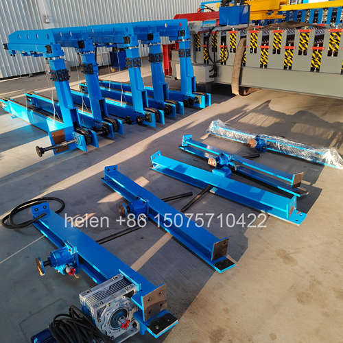
| Automatic Sheet Stacking System | Motorized stacking arm mechanism transfers finished steel sheets from the discharge conveyor table to neatly aligned product bundles on a waiting pallet, eliminating manual sheet handling labor and reducing operator fatigue during long production shifts |
| Powered Coil Transport Trolley | Battery-electric powered cart operating on floor-mounted guide rails with hydraulic scissor lift platform; safely transports steel coils weighing up to 10 tons from warehouse storage to the decoiler mandrel without requiring overhead crane equipment |
| IoT Remote Monitoring Gateway | 4G cellular-connected module transmits real-time sheet making production data — daily sheet output count, motor operating hours, fault diagnostic codes, and scheduled maintenance interval alerts — to a dedicated smartphone application or web-based production dashboard |
| Custom Embossing Roller Station | Specially engraved forming roller pair integrated into the making sequence that permanently imprints a manufacturer brand name, company logo, or production date code into each steel sheet during the making process |
| Stainless Steel Roller Upgrade | Complete sheet making roller set manufactured from grade 304 or 316L austenitic stainless steel for steel sheet production in food-grade processing facilities, pharmaceutical manufacturing plants, chemical industry environments, or high-salinity coastal sheet making operations |