helen@hbxinnuorollforming.com
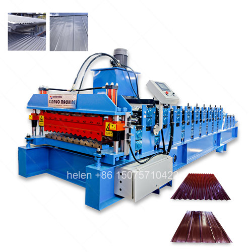
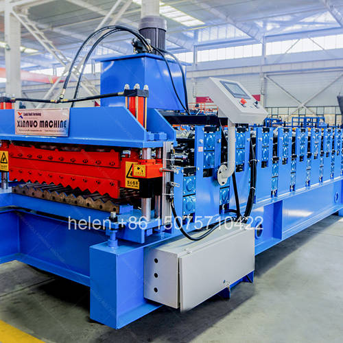
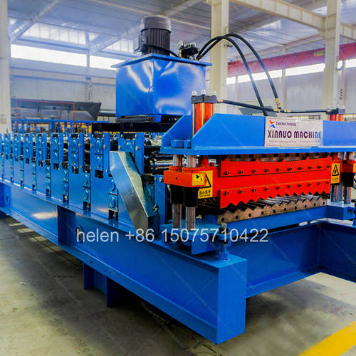
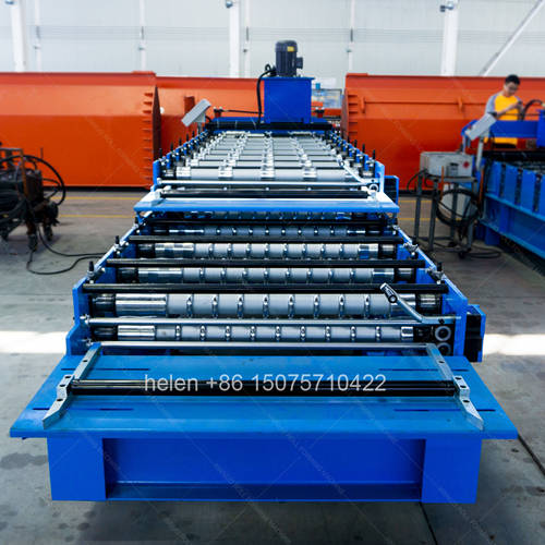
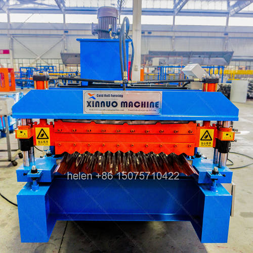
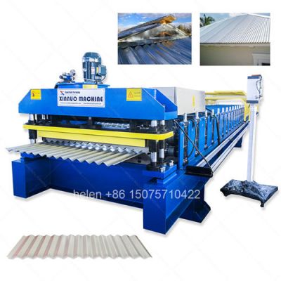
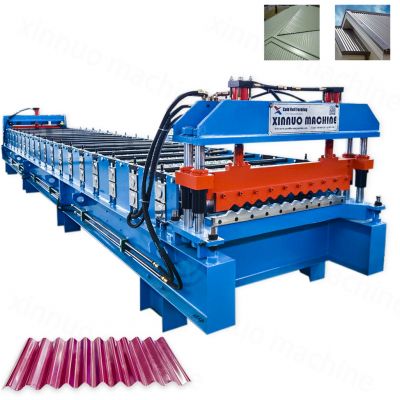
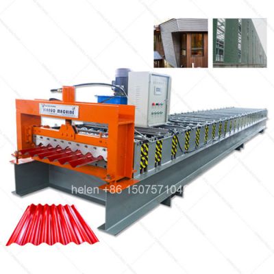
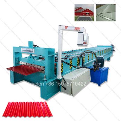
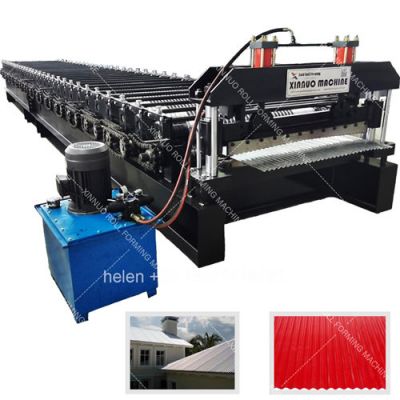
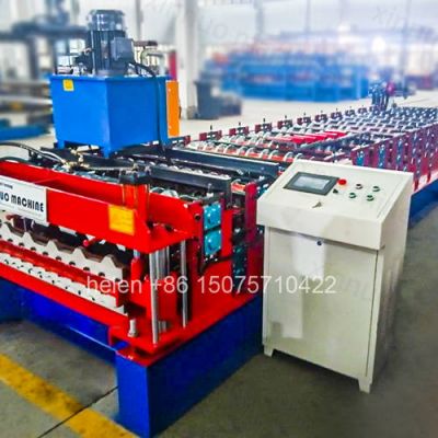
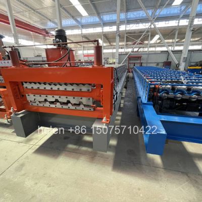
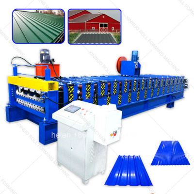
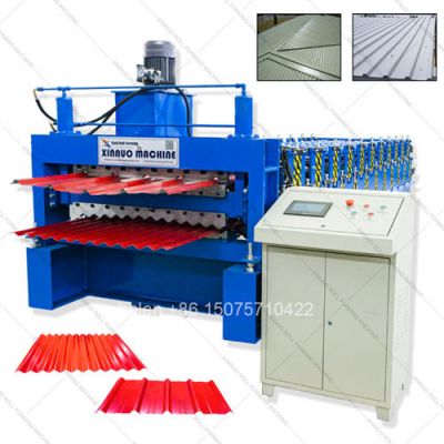
- Two forming decks stacked vertically inside one welded structural machine frame
- Upper and lower decks carry independent roller sets for different sheet profiles
- Each roller station takes a small incremental bend to avoid coating fracture
- Roller gap is set within 1.0 to 1.1 times material thickness on forming passes
- Spring-back compensation is machined into final-station rollers during tooling build
- Hard chrome surfaces at HRC 58 to 62 resist wear across millions of running metres
- Deck selection is made at the entry guide, without touching any roller
Two machines built to the same drawing, with the same motor, the same frame grade, and the same control system, can produce visibly different sheets. One runs clean trapezoidal profiles hour after hour; the other drifts into wavy edges, uneven rib height, or cracked paint along the bend lines. The difference almost never lies in the machine structure. It lies in the roller tooling — how the total deformation is distributed across the stations, how much spring-back is compensated at the final pass, how the roller gap is set against the actual coil gauge, and how the roller surfaces are finished and maintained. For a double deck roll forming machine, this discipline is applied twice, because two independent roller sets share one frame, one drive train, and one line speed.
This page sets out the tooling engineering rules that govern forming quality on both decks, so that a buyer can interrogate a machine quotation at the level where sheet quality is actually determined — rather than accepting "45# steel, hard chrome" as a complete answer.
A roofing profile is not formed in one bend. The flat coil strip passes through a sequence of roller stations, each adding a controlled increment of bend until the finished cross-section emerges at the last station. If a single station attempts too much deformation at once, the material stretches locally, the metallic coating thins beyond recovery, and pre-painted surfaces crack along the bend line. The table below sets out how deformation is normally distributed for the profile families commonly run on a double deck machine.
| Profile Family | Bend Increment per Station | Typical Station Count | Severity Assessment | Tooling Consequence |
|---|---|---|---|---|
| Shallow corrugated wave | 10° – 15° | 11 – 14 | Low | Fewest stations of any family. Wave depth is shallow relative to pitch, so each bend is gentle. Coating stress is minimal; pre-painted coil of standard ductility forms without difficulty. |
| Trapezoidal, 28 – 35 mm rib | 8° – 12° | 14 – 16 | Moderate | Rib corners are the stress points. Corner radii must be held generous to protect coating integrity, and intermediate stations must not over-bend the rib flanks. |
| Trapezoidal, 38 – 43 mm rib | 6° – 10° | 16 – 18 | High | Deep ribs demand more stations and tighter process discipline. Insufficient stations on a deep-rib profile is the single most common cause of cracked paint at the rib base. |
| Arc wave | 7° – 12° | 12 – 16 | Moderate | Continuous curvature rather than discrete corners. Roller contour accuracy matters more than station count; the smooth wave shape tolerates moderate increments. |
| Glazed tile with pitch stamping | Formed by rollers plus intermittent press | 16 – 18 plus stamping station | High | Combines continuous forming with a discrete stamping operation. The stamping die must be timed to fall only on material that has completed its forming passes, otherwise the profile distorts at the tile step. |
Every cold-formed material springs back partially after the bending force is removed. If rollers are machined as a simple inverted copy of the finished sheet, the formed sheet will be more open than the drawing — rib angles will not close, and the effective width will drift wider. The compensation for this is designed into the tooling, not adjusted on the machine.
| Factor | Typical Range | How It Is Handled in the Tooling |
|---|---|---|
| Spring-back amount | 2° – 8° total | Driven by material yield strength and by the ratio of bend radius to material thickness. Higher yield strength and larger radius both increase spring-back and require more compensation. |
| Over-bend at final stations | 1° – 5° added | The last two or three stations are machined with deliberate over-bend so that the material relaxes into the correct final angle rather than short of it. |
| Effective width correction | Profile-specific | Flange lengths on the final station rollers are shortened so the sheet relaxes to the specified cover width rather than exceeding it. |
| Coating sensitivity | Radius factor 1.0t – 2.0t | Pre-painted coil requires a larger minimum inside radius than bare steel to prevent paint cracking. Polyester coatings tolerate a smaller radius than PVDF, so tooling designed for one coating system may not suit the other. |
| Material thinning at bends | 5% – 15% | Thinning increases as the bend radius tightens. Tooling contour must account for reduced wall thickness at the rib corner, otherwise the finished profile measures undersize at the stress point. |
The practical consequence for a buyer is straightforward. Tooling designed for bare galvanized coil will generally produce acceptable results on bare coil. The same tooling applied to pre-painted coil in a heavier gauge, or to a higher-yield material, may produce coating cracking at the rib base. Where a machine is intended to run pre-painted material across the full gauge range, the tooling should be engineered for that condition at the point of order, not corrected afterwards.
The gap between the upper and lower roller of each station controls how much the material is squeezed as it passes. Set too wide, the profile forms incompletely. Set too tight, the material is over-compressed, the coating is burnished or scraped, and the rollers themselves wear abnormally at the contact edge. The setting is not arbitrary — it follows a ratio against the actual material thickness.
| Station Position | Gap Ratio to Material Thickness | Purpose and Risk If Set Incorrectly |
|---|---|---|
| Early forming stations | 1.05t – 1.15t | Material must slide freely while the first bends are introduced. Too tight here causes drag, coating scuffing, and distorted entry geometry. |
| Intermediate stations | 1.02t – 1.08t | Progressive control of the developing profile. This is where most gauge adjustment is made when the coil supplier changes. |
| Final forming stations | 0.98t – 1.02t | Final sizing of dimensions. Slight compression here holds the profile to drawing after spring-back. |
| Roller gap variation across width | Not to exceed 0.02 mm | Uneven gap from one side of the roller to the other produces a sheet that is tighter on one edge — visible as a curl or as uneven rib height across the panel width. |
| Element | Standard Specification | Why It Matters in Service |
|---|---|---|
| Roller body material | 45# forged carbon steel billet | Forging closes internal porosity that cast or bar stock may retain. A forged roller resists the cyclic forming load without developing subsurface cracks that would eventually reach the working surface. |
| Contouring method | CNC lathe turning to profile drawing | Determines whether every roller in a set produces identical geometry. Hand-finished or template-copied rollers introduce station-to-station variation that accumulates along the forming line. |
| Profile tolerance | ±0.03 mm to ±0.05 mm | Directly controls finished sheet dimensional consistency. Tighter tolerance on the roller translates to tighter consistency from the first sheet to the last sheet of a production run. |
| Surface preparation | Ground before plating | A ground substrate lets the chrome layer bond evenly. Plating directly onto a turned surface produces an uneven layer that wears through in patches. |
| Chrome layer | Hard chrome, 0.03 – 0.05 mm, HRC 58 – 62 | The chrome surface has higher hardness than the paint system it contacts, so it slides against pre-painted coil without abrading it. On bare galvanized coil it resists zinc adhesion and pickup. |
| Working surface finish | Mirror polished | Determines whether the roller transfers its own surface texture onto the sheet. A rough or pitted surface leaves a visible mark on the finished panel regardless of material type. |
| Bore and keyway | H7 bore, keyway to GB/T 1095 | Guarantees concentric mounting on the shaft. A loose bore allows the roller to run eccentric, which produces cyclic thickness variation along the sheet length. |
| Edge treatment | Chamfered and radiused | Sharp roller edges mark the coil strip at the sheet edge — a defect that becomes visible as a bright line once the roof is installed. |
| Component | Specification | Engineering Rationale |
|---|---|---|
| Shaft diameter | Φ75 mm or Φ80 mm solid steel | Shaft diameter sets the deflection limit. On the lower deck, the shaft also carries the additional load transferred through the shared frame, so undersized shafts bend slightly under load and the roller gap opens at mid-width. |
| Shaft tolerance and finish | Centerless ground to h6 | Matches the H7 roller bore to produce a controlled interference-free fit that still prevents rotational slip. |
| Bearing type | Dual-row self-aligning spherical roller bearing | Self-aligning capability compensates for minor frame deflection that the stacked deck architecture introduces. Rigid bearings in the same position would be preloaded by that deflection and fail early. |
| Bearing housing | Split pillow block, bolted to side panel | Split housings allow bearing replacement without removing the shaft or the roller — a significant advantage when servicing the lower deck, which is harder to access than the upper deck. |
| Lubrication | Grease, Zerk fittings, lip seals | Lip seals prevent grease from migrating onto the roller working surface, where it would transfer to the coil strip and create smudge marks on finished panels. |
| Drive coupling | Keyed sprocket, hardened teeth | Must transmit the full forming torque without backlash. Any rotational play between sprocket and shaft appears as speed fluctuation at the roller, producing periodic thickness variation. |
| Lifecycle Stage | Typical Interval | Action and Decision Point |
|---|---|---|
| Routine inspection | Annually, or on visible defect | Inspect every roller working surface under raking light for chrome peeling, pitting, and wear bands. Record roller diameter at multiple points so wear trend can be tracked over years. |
| Roller diameter measurement | Annually, logged | Wear is progressive and slow. Logged measurements reveal the rate, which allows re-plating to be scheduled during a planned shutdown rather than at an unplanned failure. |
| Chrome re-plating | When chrome is breached | Once chrome has worn through to the steel substrate in any area, the roller must be stripped, re-ground, and re-plated. Continued running with breached chrome accelerates wear rapidly and begins marking sheets. |
| Re-plating cycles available | Typically 2 – 3 times | Each re-plating cycle removes a small amount of base material during re-grinding. After the available cycles are consumed, the roller diameter falls below the minimum that maintains correct forming geometry, and the roller must be replaced. |
| Full roller set replacement | End of re-plating life | Replacement is normally carried out as a complete set, not roller by roller, so that station-to-station geometry remains consistent and the forming line does not develop a dimensional step. |
| # | Verification Item | Acceptance Basis |
|---|---|---|
| 1 | Roller drawing availability | Profile drawings for every roller should be available on request, with each roller identified by station number |
| 2 | Station count verification | Counted stations should match the count stated for the profile family, with no station omitted to reduce cost |
| 3 | Profile dimensional check | Full profile measurement on sheets from a continuous run, not on a single hand-picked sample sheet |
| 4 | Consistency across a run | Measure the first, middle, and last sheet of a sustained run; dimensions should not drift as the rollers warm |
| 5 | Coating integrity | Inspect formed pre-painted sheets under raking light for hairline cracking at the rib base and at the sheet edge |
| 6 | Edge condition | Check both sheet edges for marking, bright lines, or coating removal that would indicate sharp or misaligned roller edges |
| 7 | Deck-to-deck comparison | Run both decks with equivalent material and confirm each achieves drawing tolerance independently |
| Parameter | Standard Range |
|---|---|
| Machine architecture | Two forming decks stacked vertically in one frame, sharing drive motor, shear, and control system |
| Available deck pairings | Trapezoidal plus trapezoidal, trapezoidal plus glazed tile, arc plus trapezoidal, arc plus glazed tile, arc plus arc, and triple deck |
| Roller stations per deck | 11 – 18 rows depending on profile family and rib depth |
| Bend increment per station | 6° – 15°, decreasing as rib depth increases |
| Roller material | 45# forged carbon steel, CNC turned, ground, hard chrome plated |
| Roller profile tolerance | ±0.03 mm to ±0.05 mm |
| Chrome specification | 0.03 – 0.05 mm layer thickness, HRC 58 – 62 |
| Roller bore | H7 with keyway to GB/T 1095 |
| Shaft | Φ75 mm or Φ80 mm solid steel, centerless ground to h6 |
| Bearing | Dual-row self-aligning spherical roller bearing in split pillow block housing |
| Roller gap on forming passes | 1.02t – 1.15t against actual coil thickness |
| Roller gap on final stations | 0.98t – 1.02t against actual coil thickness |
| Spring-back compensation | 1° – 5° over-bend machined into final station rollers |
| Main frame grade | 300H, 350H, 400H, or 450H welded H-section steel |
| Drive transmission | Duplex roller chain with hardened sprockets and selector clutch for deck engagement |
| Main motor | 5.5 kW, 7.5 kW, or 11 kW with variable frequency drive |
| Forming speed | 8 – 20 m/min depending on profile and gauge |
| Material capability | PPGI, PPGL, galvanized, aluminium-zinc coated, pre-painted aluminium; 0.30 – 0.80 mm standard |
| Cutting system | Hydraulic post-cut shear, Cr12MoV blades at HRC 60 – 62 |
| Cut length tolerance | ±1.5 mm |
| Control system | PLC with 7 in colour touchscreen HMI, independent recipe banks per deck |
| Electrical supply | 380 V / 50 Hz / 3-phase standard; alternative voltages by destination |
| Certification | CE marking, ISO 9001:2015 compliant manufacturing |
Coil loading, deck selection at the entry guide, progressive forming, length measurement, hydraulic cutting, and discharge to the run-out table proceed in the established sequence, with deck changeover completed in minutes and no tooling disturbance.
Hebei Xinnuo is a professional cold roll forming machinery manufacturer with 20+ years of experience. We specialize in C/Z purlin machines, roof panel roll formers, floor deck machines, and custom profile solutions — exported to 50+ countries worldwide.