helen@hbxinnuorollforming.com
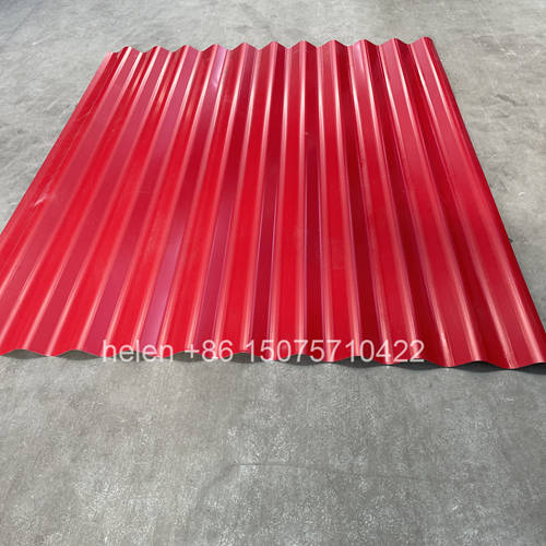
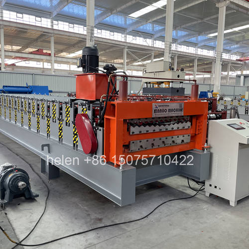
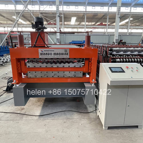
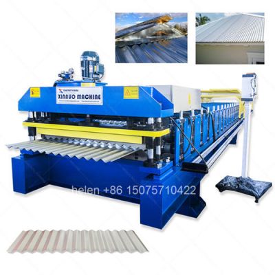
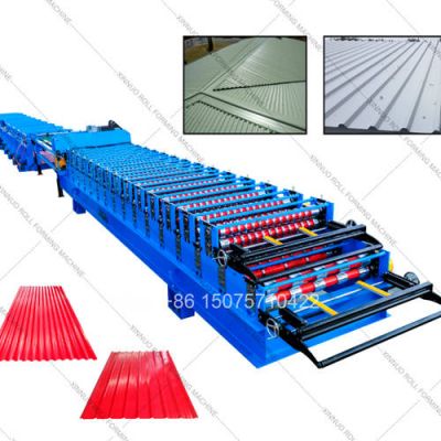
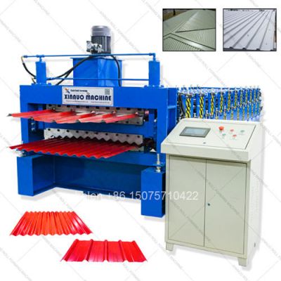
Single machine makes two types of metal roofing panels alternately
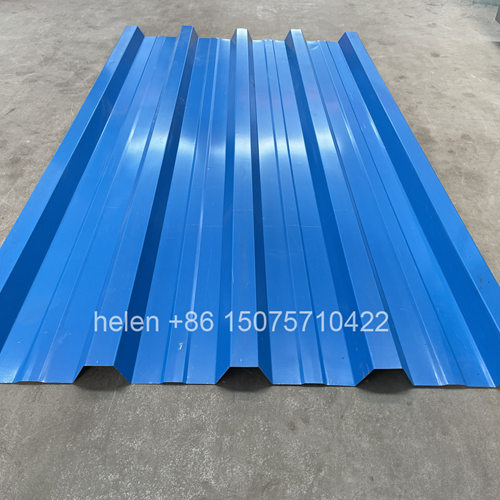
IBR trapezoidal sheets from upper deck corrugated from lower deck
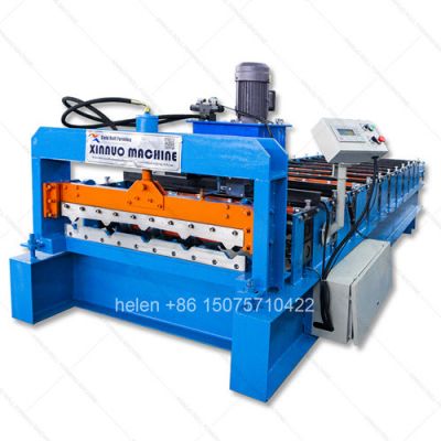
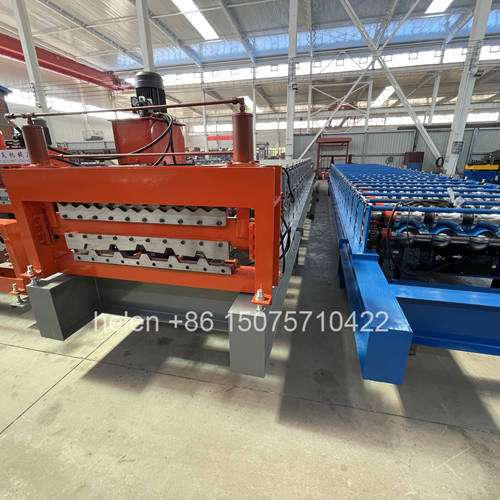
Welded steel chassis with thermal stress relief for long service life
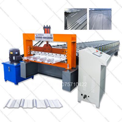
PLC controller sets panel length batch quantity and tracks production
Hydraulic shear cuts through profile at line speed without interruption
Chrome plated rollers preserve zinc and paint coating on strip surface
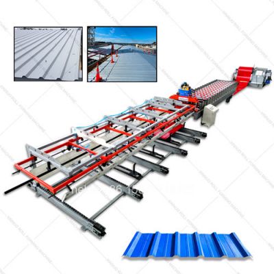
Decoiler forming machine and run-out table included in one shipment
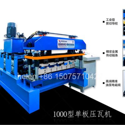
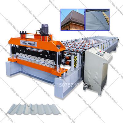
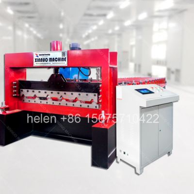
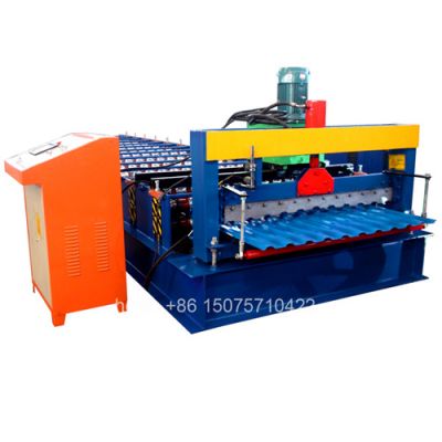
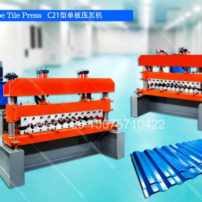
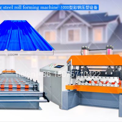
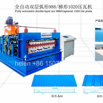
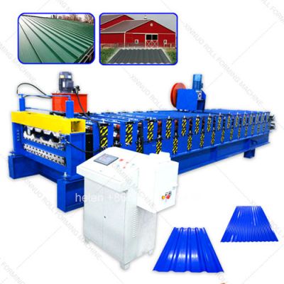
This double layer roll making machine is engineered to manufacture two types of finished metal roofing panels from a single production station. The upper roller assembly produces IBR (Inverted Box Rib) trapezoidal profile sheets — characterized by deep stiffening ribs that provide exceptional span strength for industrial and commercial roofing applications. The lower roller assembly manufactures traditional corrugated wave profile sheets — the classic sinusoidal metal panel used in residential construction, agricultural buildings, and budget-sensitive projects across global markets. By housing both manufacturing capabilities in one frame, the machine halves the equipment footprint and investment required to offer two roofing product lines.
| Product Attribute | IBR Trapezoidal Roof Panel | Corrugated Wave Roof Panel |
|---|---|---|
| Panel Cross-Section | Trapezoidal ribs with flat valleys between | Continuous sinusoidal wave pattern |
| Finished Width Range | 762mm to 1100mm effective cover | 660mm to 1000mm effective cover |
| Rib/Wave Height | 28mm to 43mm rib crown depth | 12mm to 18mm wave amplitude |
| Rib/Wave Quantity | 4 to 6 ribs across panel width | 5 to 11 waves across panel width |
| Standard Length | Custom cut 1m to 14m per PLC program | Custom cut 1m to 14m per PLC program |
| Primary Application | Structural roofing, warehouses, factories, commercial buildings | Residential roofing, farm sheds, wall cladding, fencing |
| Load-Bearing Capacity | High — deep ribs provide long-span strength | Moderate — suited to shorter rafter spacing |
| Regional Market Names | IBR sheet, box rib panel, trapezoidal roof sheet | Mabati, zinc sheet, GI corrugated, wave panel, iron sheet |
| Coil Material Type | Thickness Acceptable | Surface Coating | Typical Source |
|---|---|---|---|
| Hot-Dip Galvanized Steel | 0.25–0.80mm | Zinc coating Z60–Z275 g/m² | Most common; economical; wide availability globally |
| Pre-Painted Galvanized (PPGI) | 0.30–0.70mm | Polyester, SMP, or PVDF paint over zinc primer | Premium colored roofing; residential and architectural |
| Aluzinc / Galvalume (AZ) | 0.30–0.70mm | 55% Al, 43.4% Zn, 1.6% Si alloy coating | Coastal zones; high-corrosion environments |
| Cold-Rolled Steel (Bare) | 0.25–0.60mm | None — requires post-painting by buyer | Lowest cost; interior partitioning; temporary structures |
| Aluminum Alloy Sheet | 0.40–0.80mm | Mill finish or pre-painted | Lightweight roofs; chemical plants; food processing facilities |
| Mechanical System | Construction Detail | Engineering Purpose |
|---|---|---|
| Base Frame | Welded heavy channel steel, cross-braced, machined top face | Provides rigid flat mounting plane for all roller stations |
| Upright Columns | H-beam steel, bolted and welded to base, two rows per deck | Carries vertical load of upper deck plus dynamic forming forces |
| Shaft Bearing Blocks | Split cast iron pillow blocks, bolt-down to machined pads | Allows individual shaft removal without disturbing adjacent stations |
| Upper Forming Deck | 14–18 roller pairs in IBR contour, 250–300mm station pitch | Progressive bend sequence shapes flat strip into trapezoidal rib panel |
| Lower Forming Deck | 13–16 roller pairs in wave contour, 250–300mm station pitch | Progressive bend sequence shapes flat strip into sinusoidal wave panel |
| Main Motor Assembly | 5.5kW/7.5kW AC motor + worm gearbox, dual output shafts | Single power source drives both decks via separate chain loops |
| Chain Drive System | Double-row roller chain, hardened sprockets, independent tensioners | Transmits torque to each shaft with synchronized speed across deck |
| Control Component | Specification | Operator Function |
|---|---|---|
| PLC Central Processor | Siemens S7-1200 / Delta DVP / Mitsubishi FX3U | Executes all machine logic: start, stop, speed, length, count |
| VFD Inverter | Matching brand to PLC, 0–50Hz output range | Stepless speed regulation; ramp-up and ramp-down control |
| Touchscreen HMI | 7-inch or 10-inch color LCD, multi-language UI | Input sheet length, batch quantity, speed; view production counter and alarms |
| Rotary Encoder | Incremental type, mounted on final forming shaft | Measures actual sheet travel; provides real-time pulse count to PLC |
| Limit Switches | Mechanical roller-lever type, 2 per deck | Shear carriage home position detection and over-travel safety protection |
| Emergency Stop Circuit | Red mushroom-head pushbuttons, 3 positions | Instant motor and hydraulic power cutoff from any operator station |
| Cutting Subsystem | Component Detail | Performance Metric |
|---|---|---|
| Hydraulic Power Unit | 4.0kW motor + gear pump + 80L reservoir + oil cooler | Working pressure 16–21 MPa; flow rate 14–18 L/min |
| Shear Carriage | Linear rail-guided sled with pneumatic sheet clamp | Clamp force sufficient to hold sheet during blade penetration |
| Cutting Blade | Cr12MoV cold-work die steel, vacuum heat treated | Hardness HRC 60–64; service life approx. 500,000 cuts |
| Blade Geometry | Profile-matched upper and lower blade set | Cuts clean through ribs/waves without crushing the profile |
| Carriage Drive | Pneumatic return cylinder or spring-return mechanism | Cycle time under 2 seconds; ready for next cut immediately |
| Specification | Standard Value |
|---|---|
| Compatible Coil Width (Flat) | IBR: 1000–1250mm / Corrugated: 914–1220mm |
| Coil Inner Diameter | Φ508mm (standard) or Φ610mm with decoiler adapter |
| Maximum Coil Weight | 5 tons or 8 tons depending on decoiler model selected |
| Material Gauge Range | 0.25mm (30-gauge) to 0.80mm (20-gauge) |
| Production Speed | 10–18 m/min, infinitely adjustable via VFD dial |
| Cut Length Range | 1.0m minimum to 14.0m maximum per sheet |
| Length Accuracy | ±1.0mm at any cut length within range |
| Profile Switch Duration | Approx. 10–15 minutes (diverter reposition + re-threading) |
| Machine Dimensions (L×W×H) | 7.0–8.0m × 1.4–1.6m × 1.7–2.0m |
| Net Machine Weight | 5.0–7.5 metric tons (profile configuration dependent) |
| Power Supply Standard | 380V / 50Hz / 3-Phase (custom voltage and frequency per order) |
| Total Installed Power | Approx. 10–12 kW (main motor + hydraulic pump combined) |
| Station Order | Equipment Unit | Floor Space (Approx.) | Role in the Line |
|---|---|---|---|
| 1 | Hydraulic Coil Uncoiler | 2.0m × 1.5m | Holds and pays out the steel coil under controlled tension |
| 2 | Entry Guide + Pre-Shear | 1.0m × 0.8m | Centers strip and trims coil head before forming |
| 3 | Main Double Layer Roll Making Unit | 8.0m × 1.6m | Upper deck forms IBR; lower deck forms corrugated; hydraulic shear mounted at exit |
| 4 | PLC Control Cabinet | 0.6m × 0.5m | Electrical and automation control center |
| 5 | Run-Out Roller Table | 3.0–5.0m × 0.8m | Receives and supports cut panels for operator collection |
| Step | Operation Name | Detailed Action |
|---|---|---|
| 1 | Coil Setup | Steel coil is mounted onto the uncoiler mandrel; hydraulic jaws expand to grip the coil inner bore firmly; brake resistance is set to maintain stable material tension during pay-off |
| 2 | Strip Threading | Coil leading edge passes through adjustable entry side guide rollers to center on machine centerline; manual guillotine pre-shear trims the coil head square before entering the forming deck |
| 3 | Profile Selection | Operator pivots the diverter guide plate upward to route strip into the IBR upper deck or downward to route into the corrugated lower deck. Deck changeover takes approximately 10 minutes |
| 4 | Progressive Roll Forming | Flat strip advances through successive roller stations; each station incrementally bends the metal a few degrees more until, at the exit station, the full IBR trapezoidal or corrugated sinusoidal profile is achieved |
| 5 | Length Measurement | Rotary encoder on the final drive shaft sends continuous pulse signals to the PLC; the controller tracks the running sheet length in real time against the operator-preset target value |
| 6 | Automatic Cut Cycle | When preset length is reached, the PLC commands the shear carriage to clamp the sheet and travel synchronously with the moving panel; the hydraulic cylinder drives the blade through the profile; carriage and blade then return to the home position |
| 7 | Panel Stacking | The separated finished panel slides onto the run-out roller table; the operator lifts the sheet and places it onto the finished-product pallet or bundle stack for packaging and dispatch |
| Cost Element | Option A: Two Dedicated Roll Making Machines | Option B: One Double Layer Roll Making Machine |
|---|---|---|
| Purchase Investment | 100% of two-machine total price | 65–75% of two-machine total price |
| Workshop Area Needed | 44–70 m² for both lines | 20–35 m² for one line |
| Sea Freight Cost | Two container loads, double freight bill | One container load, single freight bill |
| Foundation Construction | Two separate concrete anchor pads | One concrete anchor pad |
| Workers Required | 3–4 operators for two lines | 1–2 operators per shift |
| Electricity Consumption | Two motors + two pumps running simultaneously | One motor + one pump; approx. 40% less energy |
| Maintenance & Spare Parts | Two separate maintenance calendars and spare inventories | One unified maintenance schedule and spare kit |
Every completed roll making machine undergoes a three-stage factory acceptance protocol before export crating. Stage one is dimensional verification: all roller gaps are checked with calibrated feeler gauges against the engineering tolerance table; shaft concentricity is measured at each bearing point with dial indicators; frame levelness is confirmed using precision spirit levels and laser alignment tools. Stage two is a four-hour continuous dry run at full rated speed: bearing temperatures are logged every 30 minutes using infrared thermometers; chain engagement is monitored for smoothness visually and audibly; the PLC is cycled through every programmed function — start, stop, length set, batch count, emergency stop, recipe recall — to confirm full system integration. Stage three is live production testing: factory technicians feed actual galvanized steel coil and manufacture 50 IBR panels followed by 50 corrugated panels, measuring length, rib geometry, wave spacing, and cut edge quality on every 10th sheet with digital instruments. Only machines achieving zero out-of-tolerance results across all three stages are approved for packaging and shipment.
The main machine body is first wrapped in VCI anti-corrosion film, then cushioned with dense foam padding at all corners and protruding components, followed by heavy-gauge polyethylene shrink wrap for moisture protection. The wrapped unit is bolted to a reinforced fumigated plywood pallet or welded steel export skid. All auxiliary equipment — hydraulic uncoiler, run-out conveyor table, hydraulic power pack, and electrical control cabinet — is packed individually in marked fumigated wooden crates with internal bracing. A separate small accessories crate contains the operator tool kit, spare wearing parts starter pack, and one complete set of technical documentation: mechanical assembly drawings with exploded views, electrical wiring schematic with terminal identifications, PLC programming parameter guide, lubrication point chart with recommended grease specifications and intervals, and a comprehensive English-language operation and maintenance manual. Standard lead time from deposit receipt and profile drawing sign-off is 25–35 working days. Warranty is 12 months from the shipping date with optional 24-month extension available for purchase.
| Optional Item | Description and Benefit |
|---|---|
| Servo Motor Drive Package | Replace standard AC motor with programmable servo drive for higher position accuracy, smoother acceleration curves, and reduced energy consumption when the line is idling |
| Automatic Panel Stacker | Pneumatic or motor-driven stacking arm lifts finished panels from the run-out table and arranges them in neat aligned bundles on a waiting pallet, eliminating manual sheet handling |
| Motorized Coil Loading Cart | Battery-powered trolley on floor-mounted guide rails; hydraulic scissor lift raises coils up to 10 tons onto the decoiler mandrel without crane assistance |
| Remote IoT Monitoring Unit | 4G cellular module transmits real-time operating data — daily production count, motor run hours, fault codes, maintenance interval alerts — to a smartphone or web dashboard |
| Logo Embossing Roller Station | Custom-engraved forming roller that permanently imprints a brand name, logo, or production date code into each panel during the roll forming process |
| 304/316L Stainless Roller Set | Complete forming roller set manufactured from austenitic stainless steel for applications requiring corrosion-free tooling — food processing plants, marine environments, chemical industry facilities |