helen@hbxinnuorollforming.com
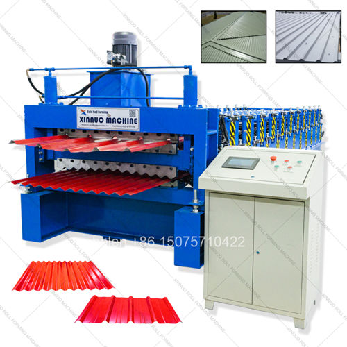
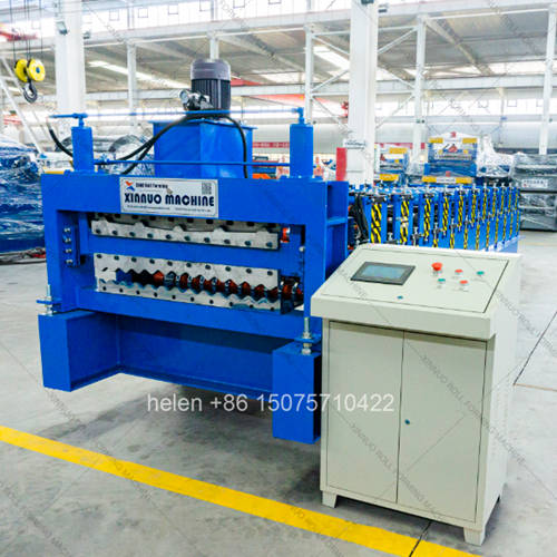
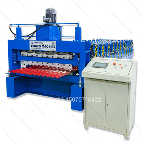
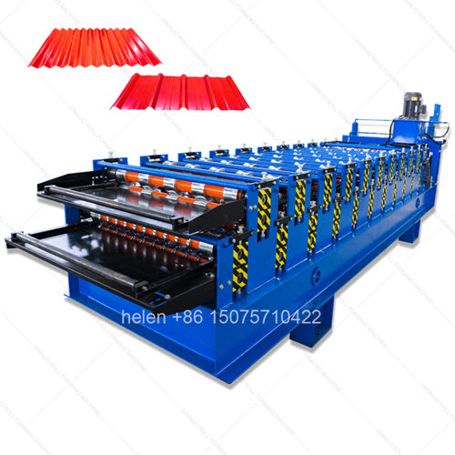
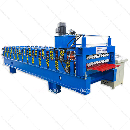
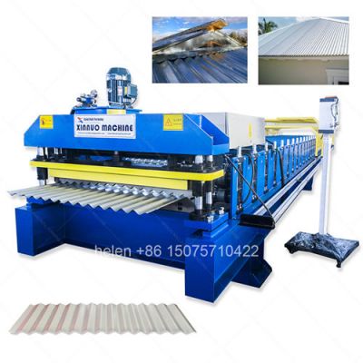
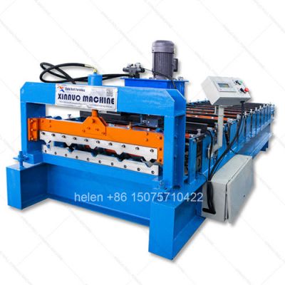
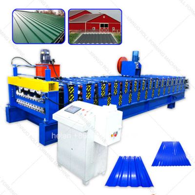
One chassis two profiles IBR and corrugated metal sheet rolling machine
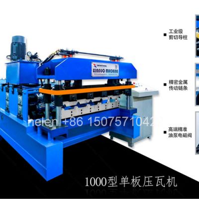
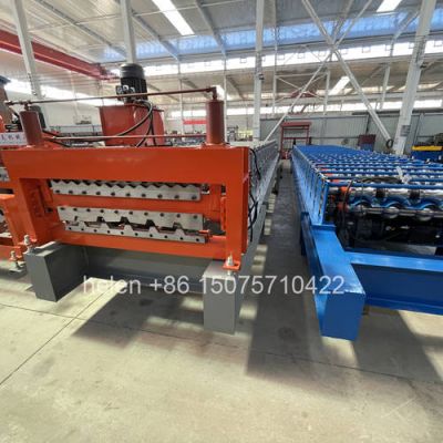
Save half workshop area with vertical stacked forming roller design
Main motor drives both decks through synchronized chain transmission system
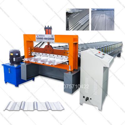
Hydraulic post-shear cuts running sheet without stopping production line
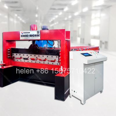
PLC length counter with batch preset automatic stop and alarm function
Forming rollers hardened and chrome plated to protect coated metal surface
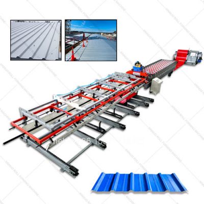
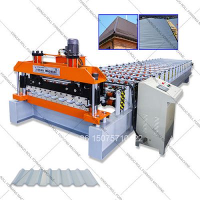
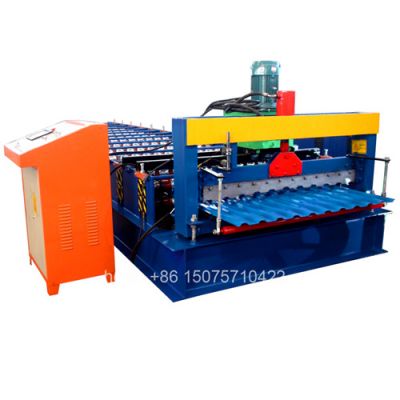
Complete line includes decoiler main machine cutting table and run-out rack
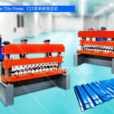
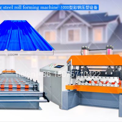
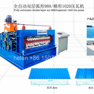
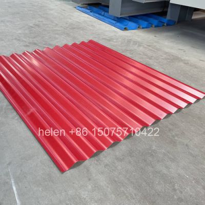
This industrial double layer roll forming machine delivers two distinct metal roofing profiles from one integrated production unit. The upper deck shapes IBR (Inverted Box Rib) trapezoidal panels used widely for structural roofing applications, while the lower deck produces traditional corrugated metal sheets favored for wall cladding, agricultural sheds, and economy roofing projects. Sharing a common drive train, hydraulic cutting system, and PLC controller, the machine provides manufacturers with a cost-effective route to offer both premium and economy metal sheet products without investing in two separate production lines.
The machine chassis is constructed from heavy-grade welded steel H-beam sections bolted to a rigid base platform. All structural welds undergo post-fabrication thermal stress-relief treatment to ensure dimensional stability over decades of continuous operation. The two roller decks are mounted one above the other at a fixed vertical offset, with the upper deck dedicated to IBR trapezoidal forming and the lower deck dedicated to corrugated wave forming. Each deck operates independently in terms of profile geometry, but both receive power from a single main motor through a dual-output gearbox that splits torque evenly between the upper and lower drive chains.
| Tooling Parameter | IBR Deck (Upper) | Corrugated Deck (Lower) |
|---|---|---|
| Forming Station Count | 14–18 rows | 13–16 rows |
| Roller Raw Material | 45# forged steel billet | 45# forged steel billet |
| Machining Method | CNC lathe with profile contour tooling | CNC lathe with wave contour tooling |
| Surface Treatment | Hard chrome plating 0.05–0.08mm | Hard chrome plating 0.05–0.08mm |
| Surface Hardness | HRC 58–62 | HRC 58–62 |
| Shaft Diameter | Φ75–Φ80mm solid alloy | Φ75–Φ80mm solid alloy |
| Bearing Type | Double-row self-aligning pillow block | Double-row self-aligning pillow block |
| Specification Item | Standard Configuration |
|---|---|
| Profile Type | Trapezoidal IBR (Inverted Box Rib) roofing panel |
| Effective Coverage Width | 762mm / 840mm / 925mm / 1000mm / 1050mm / 1100mm |
| Rib Height | 28mm to 43mm (model dependent) |
| Number of Ribs | 4, 5, or 6 ribs across panel width |
| Rib Spacing | 200mm–250mm center-to-center |
| Side Lap Detail | Single overlap with optional anti-capillary groove press |
| Specification Item | Standard Configuration |
|---|---|
| Profile Type | Sinusoidal corrugated metal wave sheet |
| Effective Coverage Width | 660mm / 750mm / 800mm / 900mm / 1000mm |
| Wave Height (Crest to Trough) | 12mm–18mm |
| Wave Quantity per Sheet | 5 to 11 waves |
| Wave Pitch | 76.2mm (3-inch standard); 60mm–100mm custom |
| End Lap Detail | 1.5-wave overlap minimum for weathertight joint |
| Technical Parameter | Performance Data |
|---|---|
| Compatible Metal Coil Types | Galvanized steel, aluzinc, Galvalume, pre-painted GI, cold-rolled steel, aluminum strip |
| Coil Thickness Range | 0.25mm–0.80mm (gauge 30 to gauge 20 equivalent) |
| Coil Width Before Forming | 1000mm–1250mm (IBR); 914mm–1220mm (Corrugated) |
| Production Line Speed | 10–18 meters per minute (VFD stepless speed regulation) |
| Main Drive Motor | 5.5kW or 7.5kW AC motor with worm gear reducer, ratio 1:40 or 1:59 |
| Hydraulic Cutting Unit | 4.0kW pump motor, 16MPa working pressure, Cr12MoV alloy blade |
| Cutting Tolerance | Length ±1.0mm; profile geometry ±0.5mm |
| PLC Controller Brand Options | Siemens S7-200/S7-1200, Delta DVP series, Mitsubishi FX series |
| HMI Touchscreen | 7-inch or 10-inch color LCD, multi-language, recipe storage |
| Chain Drive Specification | Heavy-duty double-row roller chain, fully enclosed guard housing |
| Profile Changeover Method | Manual material path switching via pivoting guide assembly |
| Changeover Duration | 8–15 minutes including strip threading |
| Electrical Power Supply | 380V 50Hz 3-phase (custom voltage/frequency per buyer country) |
| Machine Footprint (L×W×H) | 7.2m × 1.5m × 1.8m (approximate, varies by profile combo) |
| Shipping Weight | 5.0–7.5 metric tons net |
| Position | Equipment | Function |
|---|---|---|
| 1 | Hydraulic Mandrel Uncoiler | Holds metal coil up to 8 tons; active pay-off loop control maintains constant strip tension into the forming section |
| 2 | Entry Guide & Pre-shear | Side-alignment roller assembly centers the strip; manual guillotine blade trims coil leading edge square |
| 3 | Double Layer Main Machine | Upper deck (IBR rollers) and lower deck (corrugated rollers) with shared frame, drive, and cutting unit |
| 4 | Hydraulic Post-cut Station | Flying shear carriage moves synchronously with formed sheet; hydraulic cylinder drives blade through profile cross-section |
| 5 | PLC Control Cabinet | Enclosed electrical cabinet housing PLC, VFD inverter, relays, and circuit breakers; touchscreen panel mounted externally |
| 6 | Run-out Collection Table | Free-roller conveyor table receives cut sheets; operator stacks and bundles finished product |
| Stage | Action | Key Control Point |
|---|---|---|
| Coil Loading | Crane or coil car positions metal coil onto decoiler mandrel; hydraulic expansion jaws lock coil inner diameter | Coil centering to prevent strip drift |
| Strip Pay-off | Decoiler motor rotates mandrel; loop sensor feedback modulates rotation speed for steady material buffer | Loop height within sensor range |
| Feed Guiding | Strip passes through entry guide rollers; operator selects upper or lower forming path via lever-operated diverter plate | Strip centered in chosen deck entry |
| Gradual Forming | Strip advances through progressive roller stations; each station incrementally bends metal until target cross-section achieved | Roller gap = material thickness |
| Length Measurement | Rotary encoder on final shaft sends pulse count to PLC; PLC compares accumulated count against preset target | Encoder resolution and pulse accuracy |
| Cutting Execution | PLC triggers shear carriage clamp; hydraulic ram drives blade through sheet; carriage returns to home position | Carriage speed synced to line speed |
| Panel Collection | Cut sheet slides onto run-out table rollers; worker removes and stacks panel for bundling and storage | Stack alignment for bundle integrity |
| Economy Factor | Two Single-Layer Lines | One Double Layer Line |
|---|---|---|
| Initial Capital Outlay | Full price of two complete machines plus two decoilers | Approx. 65–75% of two-machine total cost |
| Workshop Floor Occupation | Approx. 44–70 m² for both lines | Approx. 20–35 m² total |
| Container Shipping Volume | 2 × 20GP (approx. 56 CBM) | 1 × 20GP or 1 × 40HQ (approx. 28–32 CBM) |
| Foundation & Civil Works | Two concrete anchor bases, two power cable runs | Single anchor base, single power cable run |
| Operating Labor | 3–4 workers across two shifts | 1–2 workers per shift |
| Annual Maintenance | Two independent maintenance routines, two spare part sets | One unified maintenance schedule, one spare kit |
| Production Mode | Simultaneous dual-profile output possible | Sequential single-profile output with quick switchover |
Each machine delivery includes a full technical documentation set in printed and digital formats: mechanical assembly blueprints with component callouts, electrical wiring diagram with terminal identification, PLC parameter configuration guide with preset recipe values, lubrication point map with recommended grease grades and intervals, plus a multilingual operation manual. Customers may optionally purchase on-site installation and commissioning service where a factory-trained technician travels to the buyer facility to perform foundation anchoring, roller gap calibration for both forming decks, PLC parameter optimization using actual customer coil material, trial production of at least 100 sheets per profile for quality sign-off, and operator classroom plus hands-on training. Standard warranty covers 12 months from the bill of lading date, with a complementary spare parts kit including one Cr12 shear blade set, 5 meters of drive chain plus master links, 2 limit switches, 2 emergency stop buttons with contacts, and one set of hydraulic cylinder seals and O-rings shipped together with the machine in the container.
| Upgrade Option | Benefit and Detail |
|---|---|
| Servo Motor Drive System | Programmable acceleration and deceleration ramps; higher length accuracy; energy savings during idle periods |
| Automatic Pneumatic Stacker | Eliminates manual sheet handling; stacks up to 50 sheets per pallet; reduces labor cost and sheet surface damage |
| Motorized Coil Loading Trolley | Rail-guided cart lifts and transports coils from storage area to decoiler; safe loading of coils up to 10 tons |
| IoT Remote Monitoring Kit | 4G cellular module sends production counters, run hours, and fault codes to smartphone app; enables predictive maintenance scheduling |
| Embossing / Branding Roller Station | Adds manufacturer logo, batch number, or pattern embossing onto the metal sheet surface during forming process |
| Flying Circular Saw Cutter | Replaces hydraulic shear for processing thicker gauge metals (0.8mm–1.5mm) with clean square-cut edges; tungsten carbide-tipped blade |
| Coil Joining / Welding Table | Manual spot-weld station between decoiler and entry guide for splicing coil tails to heads, enabling non-stop production across coil changes |