helen@hbxinnuorollforming.com
- Floor deck is cut thick, deep, and heavy, not thin sheet
- A dual-cylinder shear balances force across a long blade line
- Three-blade and two-blade options trade edge quality against waste
- Floor-level shear lets panels fall to the stack by gravity
- Cutting position allows the stack to build without manual lifting
- Edge condition affects how panels are laid and how blades wear
- Trim waste must be cleared immediately or it damages the blade
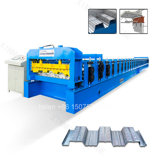
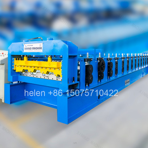
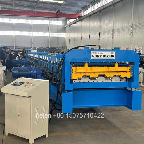
On a roof panel line, the shear is a detail. On a deck floor roll forming machine it is one of the defining subsystems, because the material being cut is a different proposition entirely: 0.8 to 1.5 mm steel formed into ribs 50 to 153 mm deep, producing panels that are long, heavy, and awkward to handle once they leave the machine. The cutting arrangement determines the quality of the edge the erector receives, how much material is lost as trim, how long the blade survives, and how much labour is required to get finished panels from the machine into a stack.
This page covers the shearing, discharge, and stacking side of a deck floor roll forming machine. It explains why cutting deep-ribbed thick material requires a different shear design from cutting roof sheet, sets out the three-blade and two-blade options and the genuine trade-off between them, describes what a dual-cylinder floor-level shear changes in daily operation, examines cut edge quality and its effect downstream on site, covers blade life and regrinding practice, addresses trim waste handling, and sets out how the discharge arrangement determines whether the machine's output rate can actually be sustained.
| Factor | Effect on the Cutting Operation | Design Response Required |
|---|---|---|
| Material thickness | Cutting 1.2 to 1.5 mm steel requires substantially more force than cutting 0.5 mm roof sheet | Higher cutting force, which a single cylinder cannot deliver evenly across a wide blade |
| Rib depth | Deep ribs mean the blade must follow a three-dimensional section rather than cut a flat sheet | Blade geometry profiled to the section, and a blade line long enough to span the full formed width |
| Panel weight | A finished deep-ribbed panel is heavy and cannot be handled by one person from a standing position | Cutting position and discharge arranged to remove manual handling from the process |
| Cut edge function | The cut end is a finished edge that interacts with the adjacent panel during laying | Edge quality becomes a functional requirement rather than a cosmetic one |
| Production continuity | Panels are produced in long runs and stack rapidly | Discharge arrangement must clear panels at the rate the forming unit produces them |
| Blade loading cycle | Thicker material loads the cutting edge far more heavily per cut | Blade hardness and edge geometry specified for the load, with spare sets for rotation |
Both arrangements are available and the choice belongs to the buyer, because the correct answer depends on whether edge perfection or material yield matters more in that particular operation. The trade-off is real and should be understood before the machine is ordered rather than discovered after.
| Aspect | Three-Blade Shear | Two-Blade Shear |
|---|---|---|
| Cutting action | An additional blade trims the section cleanly as part of the cut | Cuts with two opposing edges, without a trimming pass |
| Cutting effort | Lower force required per cut, since the material is removed progressively | Higher force concentration at the two cutting edges |
| Edge and profile finish | The cleanest result. The panel end profile is preserved exactly, with no edge deformation | Very slight deformation at the extreme corner of the cut, described as negligible and not affecting structural performance |
| Material waste | Approximately 10 mm of trim waste is produced with every cut | No waste. Every millimetre of coil becomes sellable panel |
| Housekeeping requirement | Trim must be cleared promptly. Accumulated offcuts interfere with the blade path and will damage the blade if left | No trim to clear, removing a recurring housekeeping task and its associated risk |
| Cost per panel | Carries a material cost proportional to the number of cuts, significant in high-volume production | No per-cut material loss, so cost per panel is lower on long runs |
| Operator attention | Requires discipline to clear waste at every cut cycle | No additional attention required |
| Best suited to | Operations where visible edge quality and exact end profile are commercially important, or where cut volume is low | High-volume production where material yield dominates, and where the minimal edge deformation is acceptable to the engineer |
| If the Priority Is… | The Appropriate Choice Is… |
|---|---|
| Minimum material cost per panel | Two-blade. On continuous production, eliminating 10 mm per cut is a direct and cumulative saving. |
| Perfect cut edge and end profile | Three-blade. Where the panels are visible, or where the engineer has specified an exact end condition. |
| Lowest housekeeping burden | Two-blade. No trim means no accumulation risk and no dependence on operator discipline at each cycle. |
| Lowest cutting force on the machine | Three-blade. Progressive trimming reduces the peak load on the shear frame and cylinders. |
| Production at modest volume | Three-blade. The waste penalty is small when cut counts are low, while the edge quality benefit is immediate. |
| Panel ends not visible in service | Two-blade. Where the edge deformation cannot be seen and does not affect the structural function. |
| Design Feature | Operational Effect |
|---|---|
| Two hydraulic cylinders | Cutting force is applied at two points rather than one, so the blade line stays balanced across the full width of a wide deck panel. A single cylinder on this material tends to cut unevenly across the section. |
| Balanced loading of the blade | Even force distribution reduces localised overloading at one end of the blade, which is the usual cause of chipping and premature blade failure. |
| Lower peak force per cylinder | Two cylinders share the duty, so each operates further from its limit. This extends cylinder and seal life and reduces the hydraulic pressure required. |
| Floor-level cutting position | The shear sits at floor level, so the completed panel drops directly to the discharge and stacking position rather than being supported at working height. |
| Gravity-assisted discharge | Finished panels move to the stacking area under their own weight. No manual lifting, no panel carried across the shop floor, and no handling damage to the formed surface. |
| Reduced labour per panel | The panel reaches the stack without an operator intervening, which directly affects how many panels per shift the line can realistically produce. |
| Lower handling injury risk | Removing manual handling of long, heavy, deep-ribbed panels eliminates the principal injury risk associated with the discharge end of the machine. |
| Edge Condition | Cause | Effect on Site and on the Slab |
|---|---|---|
| Clean cut edge | A sharp blade, correct clearance, and balanced cutting force | Panels lay together properly at the lap, the end profile aligns with the adjacent panel, and no remedial work is required |
| Burred edge | A dulled or incorrectly set blade, or insufficient cutting force | Burns obstruct the lap between panels, prevent them seating properly, and present a handling hazard to erectors |
| Deformed corner | The normal characteristic of a two-blade cut at the section extremity | Acceptable where the engineer has confirmed it does not affect structural performance; it is a known and predictable result rather than a fault |
| Ragged or torn edge | Blade clearance incorrect for the material thickness being cut | Indicates the shear is not set up for the current coil, and the condition will worsen across the run if not corrected |
| Coating damage at the edge | Excessive blade friction or poor blade condition on coated stock | Exposed steel at the cut end becomes the first point of corrosion, visible on the finished floor |
| Inconsistent ends across a run | Force imbalance from a single-cylinder arrangement, or blade movement in an inadequately rigid housing | Some panels stack and lap correctly while others do not, creating sorting work on site and doubt about the whole consignment |
| Practice | Requirement |
|---|---|
| Hold a spare blade set | A second set allows production to continue on the spare while the worn set is reground, instead of stopping the line for the duration of the regrind. |
| Replace on condition, not on failure | The trigger is a visible change in the cut edge — burring or a change in cutting sound. Waiting for the blade to fail damages the blade beyond regrinding and can mark the panels. |
| Match blade hardness to the duty | Blades are specified to a hardness range for the material being cut. Too soft dulls rapidly; too hard chips and can damage the shear mechanism. |
| Check clearance at material change | Blade clearance suits a material thickness. Changing to a substantially different gauge without checking clearance is a common cause of ragged edges. |
| Regrind in a controlled sequence | Removing metal from the blade reduces its stroke, so regrinding should be tracked and the blade retired before the cut quality degrades. |
| Keep the blade area clear | On a three-blade arrangement, trim left in the blade path is a direct cause of blade damage. Clearing it is not optional. |
| Record cuts per blade set | Establishes a realistic replacement interval for the actual duty, which is the only reliable basis for ordering spares in advance. |
| Source of Waste | Typical Quantity | Handling Requirement |
|---|---|---|
| Three-blade trim | Approximately 10 mm per cut | Collected at every cut cycle. Left in place, it accumulates in the blade path and damages the blade, so the machine design and the operating procedure must both account for it. |
| Coil start and end material | A short length per coil | Discarded or used for setting up. Deciding in advance whether the coil tail is threaded or scrapped removes a decision from the middle of a changeover. |
| First panel after a changeover | One panel per change | Treat as a reference panel rather than waste. It confirms the settings before the run proceeds and can usually be used or sold. |
| Off-specification panels | Variable | Detected by checking the first panel properly. Off-specification output accumulates quickly once a run has started, and scrap is the most expensive form of waste on the line. |
| Handling-damaged panels | Avoidable | Arises from manual handling and from panels dragged across one another. A floor-level discharge and a defined stacking procedure eliminate most of it. |
| Storage marking | Avoidable | Pressure marks from stacking without interleaving appear days later in store or on site, by which time the cause is no longer visible. |
The forming unit sets the theoretical output rate, but the discharge end determines whether that rate is achieved across a shift. Panels leaving the machine must be moved away at the rate they arrive, and on a deep-ribbed deck line they cannot simply be stacked by hand.
| Element | Requirement and Effect on Output |
|---|---|
| Output bracket length | The discharge bracket must be long enough to support the longest panel produced. An undersized bracket forces the line to be stopped to clear panels, converting a production constraint into a handling constraint. |
| Gravity discharge | Floor-level cutting with gravity discharge removes the lifting step entirely, which is the single largest labour saving on the discharge end of the line. |
| Stacking position | Positioned to receive panels directly, so the panel is never lifted or turned between the shear and the stack. |
| Stack height control | Stacks build quickly and must be removed before they obstruct the discharge. A defined maximum stack height prevents the line stopping because the stack is full. |
| Lifting provision for the stack | Crane or forklift access at the stacking position, so the finished stack is removed whole rather than sheet by sheet. |
| Interleaving for coated stock | Applied as the stack is built rather than afterwards. Coated deck panels pressure-mark in storage, and the damage is only discovered at delivery. |
| Route from stack to dispatch | A direct route that does not require passing the stack back through the operating area or against the coil flow. |
| Sheet count verification | Counted as the stack is built, since the panel count is the basis for invoicing and for confirming that the run is complete. |
| Parameter | Standard Range |
|---|---|
| Profile type | Open trapezoidal deck and closed re-entrant deck, produced to the buyer's profile drawing or a matched standard section |
| Effective coverage width | 688 – 1025 mm across the standard families; wider by drawing specification |
| Rib height | 39 – 153 mm depending on profile class |
| Forming rows | 18 – 36 rows, selected against rib height, section type, and material thickness |
| Frame | 400H – 450H welded H-section with 10 mm flange thickness and a 18 – 25 mm mid plate |
| Shaft | Φ90 – 115 mm round bar, rough turned then precision ground |
| Forming wheels | 45# forged steel, quenched to HRC 45 – 50, finish turned, keyed, polished, and chrome plated |
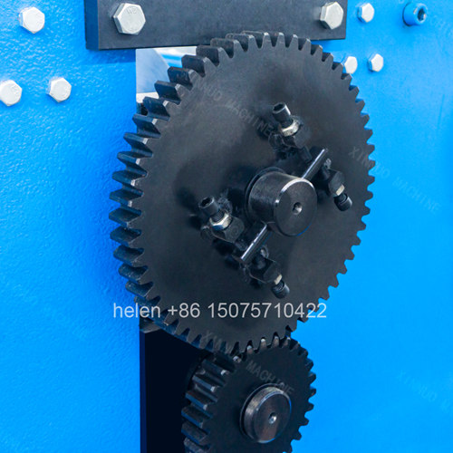
| Transmission | 2 inch external roller chain standard, 2.5 inch for the heaviest profiles |
| Motor configuration | 2 × 11 kW standard, 2 × 15 kW heavy, 2 × 22 kW above 1.5 mm material |
| Shear type | Dual-cylinder hydraulic shear with balanced force across the full panel width |
| Shear mounting | Floor level, allowing completed panels to discharge to the stacking position by gravity |
| Blade options | Three-blade for the cleanest edge with approximately 10 mm trim waste per cut; two-blade for zero waste with negligible edge deformation |
| Blade material | Alloy tool steel at HRC 60 – 62, supplied in sets with a spare set available for rotation during regrinding |
| Material capability | 0.8 – 1.5 mm standard; galvanized, aluminium-zinc coated, and pre-painted coil |
| Forming speed | 8 – 18 m/min depending on profile depth and material thickness |
| Cut length tolerance | ±1.5 mm |
| Output bracket | Approximately 3,000 mm, sized to support the longest panel produced |
| Control system | PLC with colour touchscreen HMI, sheet count control, and stored recipe banks |
| Line length | Approximately 22 m overall, with a forming unit of about 14.5 m and a forming unit width of about 2.75 m |
| Electrical supply | 380 V / 50 Hz / 3-phase standard; alternative voltages and frequencies by destination |
| Certification | CE marking and ISO 9001:2015 compliant manufacturing |
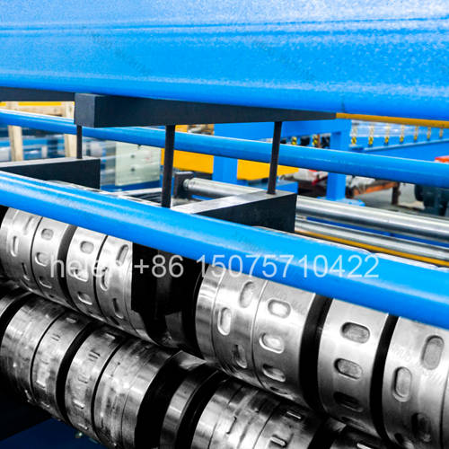
Coil loading on the decoiler, strip entry through the guide, progressive forming across the roll train with embossment at the dimple row, sizing over the final passes, length measurement, dual-cylinder cutting at floor level, and gravity discharge to the stacking position follow the established sequence, with cut length and sheet count controlled from the operator panel and the panel geometry set by the roller profile.
Hebei Xinnuo is a professional cold roll forming machinery manufacturer with 20+ years of experience. We specialize in C/Z purlin machines, roof panel roll formers, floor deck machines, and custom profile solutions — exported to 50+ countries worldwide.