helen@hbxinnuorollforming.com
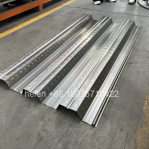
- A stacked deck machine is a custom project, not a catalogue purchase
- The decisions that cause problems are made in the first few weeks
- Both profiles must be defined before engineering starts
- Row count and feed width matching decide whether the combination works
- Drawing approval covers two sections and two sets of tooling
- The pre-shipment test must run both decks, not just one
- Commissioning both decks takes longer than buyers expect
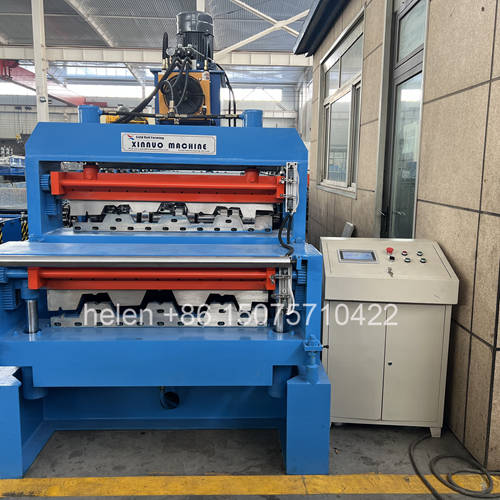
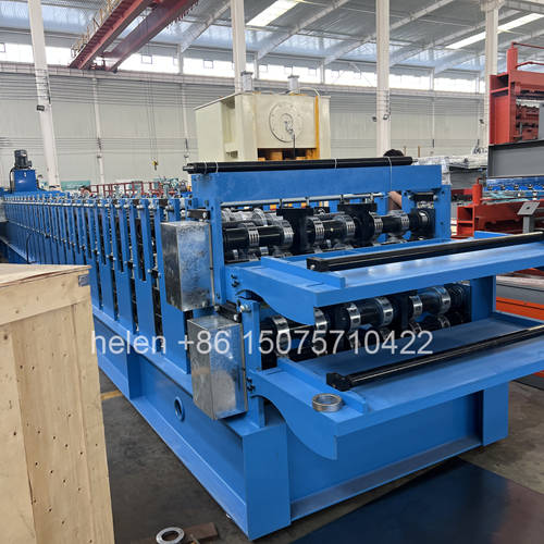
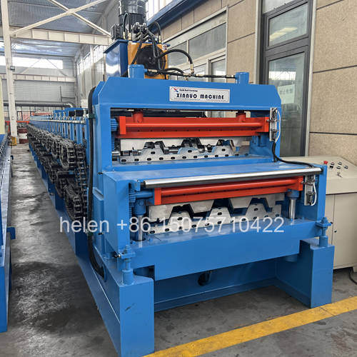
A double layer floor decking machine is not ordered from a stock list. Two complete deck forming trains are built into one frame, each with its own tooling, its own embedded provision, and its own section drawing, and the two have to work together on a single shared drive. That makes it a custom engineering project, and like most custom engineering projects, the decisions that determine whether it succeeds are made in the first few weeks rather than on the assembly floor.
This page sets out the sequence a stacked deck machine project actually follows, from the point at which a requirement is defined to the point at which a trained crew is producing both profiles to specification. It identifies what has to be established at each stage, who is responsible for it, what evidence demonstrates that the stage is complete, where the recurring mistakes occur, and what the buyer has to supply at each point. It is written for buyers running a project of this kind for the first time, and for those who have run one before and want the sequence set out explicitly rather than managed by memory.
| What to Establish | Why It Matters at This Stage | Common Error |
|---|---|---|
| The two profiles, by drawing | Both sections must be known before any engineering begins. Rib geometry, rib count, pitch, lap detail and coverage width all come from the drawings. | Specifying from a familiar profile name rather than a drawing. Two sections with the same familiar name can differ materially. |
| Volume expected from each profile | Establishes whether one-at-a-time production is acceptable, which is the fundamental premise of the stacked design. | Assuming the machine will produce both profiles together. It cannot, and a project planned on the wrong assumption fails commercially rather than technically. |
| Thickness range for each profile | The most demanding layer sets the drive, the frame and the chain specification for the whole assembly. | Quoting the typical gauge instead of the maximum. The machine then underperforms at the heaviest material it is asked to run. |
| Blank width and coil supply | Determines the decoiler, the entry guide range and what coil must be purchased for each layer. | Treating feed width as equivalent to cover width. The two are different figures and the difference is the material consumed in ribs and laps. |
| Workshop headroom and floor capacity | A stacked deck machine is tall and heavy, and both increase with the second layer. | Establishing site constraints after the order is placed, when they can only be accommodated at cost or by compromise. |
| Changeover frequency expected | The recurring cost of a stacked machine is the switch between layers. Frequency determines whether that cost is trivial or decisive. | Estimating changeover in minutes without multiplying it by the number of switches per week and the value of the lost time. |
| Available commissioning window | A stacked deck machine takes longer to commission than a single deck line, and the window must be planned rather than assumed. | Booking installation into a period when the buyer's production commitments leave no room for a longer commissioning. |
Before configuration is discussed, the proposed pairing has to be assessed against the rules that govern any stacked machine. This is the stage at which an unworkable combination is identified cheaply.
| Check | Criterion | Outcome |
|---|---|---|
| Row count match | Identical counts are ideal; two to four rows difference is generally acceptable; five to eight rows requires additional motor capability or a revised chain ratio on the slower layer; beyond ten rows needs engineering assessment. | Determines whether the pairing proceeds as proposed, proceeds with a drive adjustment, or is reconsidered. |
| Feed width match | One shared coil width is ideal; a difference within roughly 50 mm can be handled by guide block adjustment; a larger difference requires two separate guiding arrangements and manual changeover adjustment. | Establishes whether the entry arrangement stays simple or becomes a changeover step in its own right. |
| Frame escalation | The frame follows the heavier layer and escalates one tier above that layer's single machine equivalent — except where the heavier layer already sits at the top of the ladder, which is the case for deck profiles. | For deck combinations this check frequently concludes that the design must be engineered around a practical ceiling rather than stepped up conventionally. |
| Chain escalation | The chain follows the higher torque demand and is normally one tier above that layer's single machine specification. | Confirms the transmission arrangement that will carry both layers in turn. |
| Per-layer provision | Each deck needs its own embossing arrangement, its own bearing-mounted rear wheels, its own reinforcement bars and its own gear drives. | Confirms that the provision is costed per layer rather than assumed to be shared. |
| Discharge compatibility | The shear and stacking arrangement must suit the heavier of the two products. | Confirms whether one discharge arrangement serves both or whether the difference is material. |
| Document | Who Approves | Why It Must Be Signed Before Manufacture |
|---|---|---|
| Section drawing for the deck layer | The buyer or the engineer specifying the section | Roll tooling is produced to this drawing. Once cut, correcting a section error means new tooling, not an adjustment. |
| Section drawing for the second layer | The buyer or the engineer specifying that section | The second profile carries the same consequence. Both drawings must be approved, not only the primary one. |
| Machine general arrangement drawing | The buyer, against their own site constraints | Confirms overall length, width, height and mass, which is what the foundation, headroom, access and lifting plans depend on. |
| Foundation and loading drawing | The buyer or their structural adviser | Point loading at the frame feet is higher than on a single machine because both layers load one base. |
| Utility requirement schedule | The buyer's electrical contractor | Supply voltage, phase, capacity and termination points must be in place before commissioning, not during it. |
| Changeover procedure outline | The buyer's production management | Confirms that the operational sequence is understood by the people who will have to live with it. |
| Spare parts and documentation list | The buyer | Parts agreed but not listed are frequently not supplied, and the omission surfaces at the first breakdown. |
| Parameter | What It Is Fixed By |
|---|---|
| Frame and mid plate | The heavier layer's forming load and the combined carriage weight of both decks. |
| Shaft diameter | The deck layer's forming load, with deflection being the governing criterion rather than strength alone. |
| Forming rows per deck | Rib height and material thickness for each profile, reconciled against the row matching rule. |
| Motor configuration | The maximum thickness on the deck layer. |
| Chain and selector | The higher torque demand of the two layers, escalated one tier above that layer's single machine specification. |
| Feed width and guiding | The blank width of each profile and the size of the difference between them. |
| Shear and blade arrangement | The heavier product, plus the buyer's choice between a cleaner cut with trim waste and zero waste with a negligible edge condition. |
| Control and recipes | Two stored recipe banks, explicit active-layer indication, and cut length and sheet count control. |
| Tier of finish and speed | The production volume the machine is expected to serve, not the profile alone. |
| What Is Verified | Evidence That Should Be Produced |
|---|---|
| Row count on each deck | A physical count against the agreed specification, not a description of the machine. |
| Drive and chain configuration | Confirmation of the motor count and rating and the chain size actually fitted. |
| Per-deck embedded provision | Confirmation of the embossing arrangement, bearing-mounted rear wheels, reinforcement bar positions and gear drive positions on each deck. |
| Test run on the deck layer | Panels produced at the upper end of the ordered thickness range, over a continuous run rather than a single sample. |
| Test run on the second layer | Panels produced on the second profile. A test that covers only one deck does not demonstrate that the second exists in working order. |
| Changeover between the decks | The switch performed and timed, with the first panel of each verified afterwards. |
| Measured panel dimensions | Cover width, rib height, rib pitch, length across a run, squareness, flatness, embossment condition and surface finish for each profile. |
| Safety function operation | Emergency stops operated and isolation verified, with restart prevention confirmed. |
| Test record | A written record of material used, settings applied and panels produced, forming the baseline against which future performance can be compared. |
| Activity | Requirement |
|---|---|
| Packing and protection | Roller sets, guide surfaces and control equipment protected against transit damage, with the two decks identified so that assembly cannot be confused. |
| Arrival inspection | Inspect before unloading where possible. Transit damage and missing items are far easier to resolve before the machine is in position. |
| Lifting and movement | Adequate capacity for the assembled frame weight, with a route from the unloading point to the final position confirmed in advance. |
| Positioning and leveling | Position set first, then leveling established longitudinally, transversely and by diagonal check, with anchoring only after level is confirmed. |
| Level recheck after anchoring | Anchoring and initial loading can both disturb the setting established before them. |
| Line alignment | Decoiler, entry guide, forming frame, shear and run-out aligned to one line. Misalignment between sections presents as a forming fault and is often misdiagnosed as one. |
| Electrical connection | Supply voltage, phase, earthing and isolation confirmed before the first start. |
| Guard and access refitting | All guards and access provision in place, including service access to the upper deck. |
| Activity | Requirement |
|---|---|
| Deck layer setup | Tooling alignment and gap setting on the first deck, using the buyer's own coil. |
| Second layer setup | The same process on the second deck, with the alignment of the first deck rechecked afterwards to confirm it was not disturbed. |
| Changeover verification | The switch performed in both directions, with the first panel of each profile measured. |
| Recipe confirmation | Stored parameters verified against the test run figures for each deck. |
| Production trial | A run in normal production conditions rather than only an engineering test, at the lengths and quantities the buyer actually expects to produce. |
| Operator involvement | The people who will run the machine performing the changeover themselves under supervision, not watching it being done. |
| Leveling recheck | Rechecked after the first production run, since anchoring and initial loading can both affect it. |
| Duration expectation | Two to three days for a standard stacked deck machine, and longer where the two layers diverge significantly in row count or forming regime. |
| Item | Requirement |
|---|---|
| Documentation handover | Machine manual, electrical and hydraulic schematics, both section drawings, parts list with component references, blade specification and the test run record. |
| Changeover procedure, written | Documented for each transition, so that the switch is a repeatable procedure rather than the knowledge of one experienced operator. |
| Stored recipes | Confirmed in the control system for both decks, with a record of the parameters in case of loss. |
| First panel acceptance criteria | Agreed and recorded per profile, so that routine production checking has a defined reference. |
| Spare parts supplied | Checked against the agreed list, with particular attention to items that exist per deck rather than once. |
| Operator training | Covering both decks, the changeover, routine checks, and what constitutes a fault worth stopping for. |
| Maintenance schedule | Per deck, including the access arrangements for servicing the upper train. |
| Site test record | Site measurements added to the factory record so the machine's own baseline covers both its pre-shipment and installed condition. |
| Mistake | Stage | Consequence |
|---|---|---|
| Specifying from a profile name rather than a drawing | Stage 1 | Tooling produced to an assumed section, which becomes a tooling replacement rather than an adjustment. |
| Planning on simultaneous production | Stage 1 | The commercial case is built on a capability the machine does not have. Stacked machines produce one profile at a time. |
| Stating the typical thickness rather than the maximum | Stage 1 | The machine underperforms precisely at the material where performance is hardest to achieve. |
| Skipping the feasibility check | Stage 2 | Row count or feed width incompatibility discovered after manufacture, when it is expensive to resolve. |
| Approving only one section drawing | Stage 3 | The second profile's tooling is produced without confirmed approval, and the error surfaces at commissioning. |
| Testing only one deck before shipment | Stage 5 | The second deck's problems are discovered in the buyer's factory, thousands of kilometres from where they could have been fixed cheaply. |
| Site not ready when the machine lands | Stage 6 | The installation team is on site but the foundation, power or access is not, and the visit is partly wasted. |
| No coil available for the second profile | Stage 7 | One deck commissions while the other is assumed to be fine, which is exactly the assumption the second test run exists to remove. |
| Operators not present for commissioning | Stage 7 | Capability is not transferred. The machine is commissioned but the crew cannot repeat what was demonstrated. |
| Changeover procedure left undocumented | Stage 8 | Changeover time drifts upward and depends on one person, which is the opposite of what the stacked design was bought for. |
| Stage | Buyer Input Required |
|---|---|
| Requirement definition | Section drawings for both profiles, volume expectations for each, full thickness ranges, coil specification, site constraints, changeover frequency estimate and commissioning window. |
| Feasibility | Timely answers on whether a proposed adjustment to row count, feed width or thickness range is acceptable to the buyer's market. |
| Drawing approval | Formal approval of both section drawings and the general arrangement, returned promptly. Every day of delay here moves the whole programme. |
| Configuration | Confirmation of the shear preference, speed tier and documentation requirements for the destination market. |
| Test run | Attendance or a nominated representative at the pre-shipment test, and confirmation of acceptance. |
| Site preparation | Foundation complete, floor loading verified, headroom confirmed, power terminated, lifting arranged and access route cleared. |
| Commissioning | Coil of the correct specification for both profiles on site, and the operators who will run the machine present for the whole period. |
| Handover | Nomination of the person who will own the machine's documentation, recipes and changeover procedure internally. |
| Parameter | Standard Range |
|---|---|
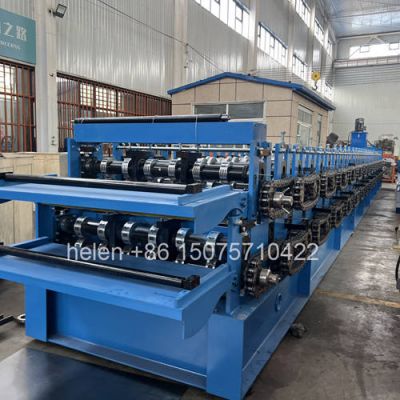
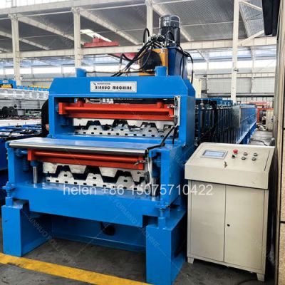
| Machine configuration | Two complete deck forming trains stacked vertically in one welded frame, sharing one transmission with a layer selector |
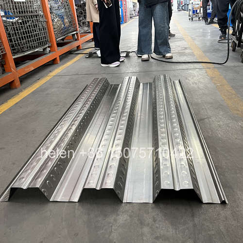
| Profile type | Open trapezoidal structural deck and closed re-entrant deck, produced to the buyer's approved drawings |
| Effective coverage width | 688 – 1025 mm per deck across the standard families; wider by drawing specification |
| Rib height | 39 – 153 mm on the deck layer, depending on profile class |
| Forming rows per deck | 18 – 36 rows on the deck layer, with the second layer specified against the row matching rule |
| Frame | 450H welded H-section with 10 mm flange thickness for a stacked deck machine |
| Mid plate | 20 – 25 mm |
| Shaft | Φ95 – 115 mm round bar, rough turned then precision ground |
| Forming wheels | 45# forged steel, quenched to HRC 45 – 50, finish turned, keyed, polished and chrome plated, supplied per deck to its own approved drawing |
| Embedded provision per deck | Embossing row with clutch arrangement, bearing-mounted oversized rear wheels, reinforcement bars at critical rows, gear drives at high-resistance positions |
| Transmission | 2 inch or 2.5 inch external roller chain with a layer selector and positive layer indication |
| Motor configuration | 2 × 11 kW to 2 × 22 kW, set by the deck layer's maximum thickness requirement |
| Feed width | Matched across layers where possible; a difference within roughly 50 mm handled by guide block adjustment |
| Layer changeover | Approximately 5 – 15 minutes to reposition the material path and verify the first panel |
| Shear | Dual-cylinder hydraulic shear at floor level, sized to the heavier product, with gravity-assisted discharge |
| Blade options | Three-blade for the cleanest edge with approximately 10 mm trim waste, or two-blade for zero waste with negligible edge deformation |
| Material capability | Deck layer 0.8 – 1.5 mm; second layer to its own profile requirement; galvanized, aluminium-zinc coated and pre-painted coil |
| Forming speed | 8 – 18 m/min on the deck layer, depending on profile depth and material thickness |
| Cut length tolerance | ±1.5 mm |
| Control system | PLC with colour touchscreen HMI, sheet count control, explicit active-layer indication and a separate stored recipe bank per deck |
| Pre-shipment test | Test run on both decks at the upper end of the ordered thickness range, plus a timed changeover between them, with a written test record |
| Commissioning duration | Approximately two to three days for a standard stacked deck machine, longer where the layers diverge in row count or forming regime |
| Electrical supply | 380 V / 50 Hz / 3-phase standard; alternative voltages and frequencies by destination |
| Certification | CE marking and ISO 9001:2015 compliant manufacturing, with destination-market documentation arranged as required |
Coil loading on the decoiler, strip entry through the guide, selection of the intended deck at the entry path, progressive forming on that deck with embossment at its dimple row, sizing over the final passes, length measurement, dual-cylinder cutting at floor level, and gravity discharge to the stacking position follow the established sequence, and the project sequence described above runs from requirement definition to a trained crew producing both profiles to specification.
Hebei Xinnuo is a professional cold roll forming machinery manufacturer with 20+ years of experience. We specialize in C/Z purlin machines, roof panel roll formers, floor deck machines, and custom profile solutions — exported to 50+ countries worldwide.