helen@hbxinnuorollforming.com
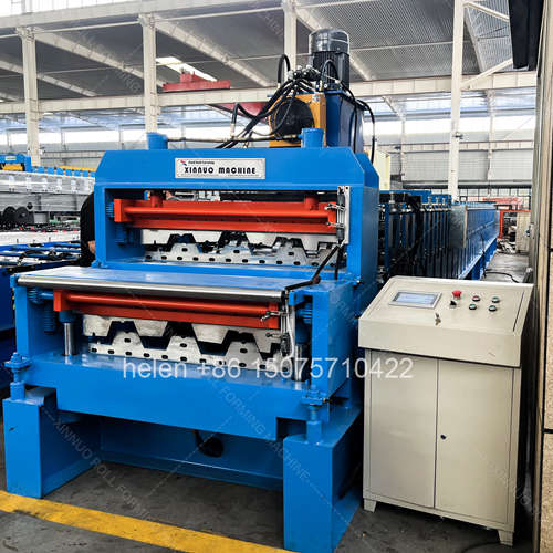
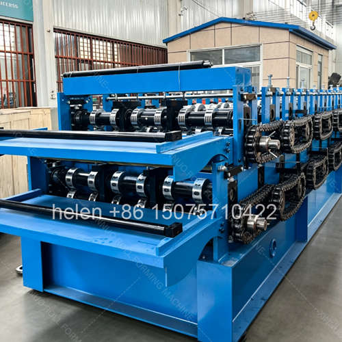
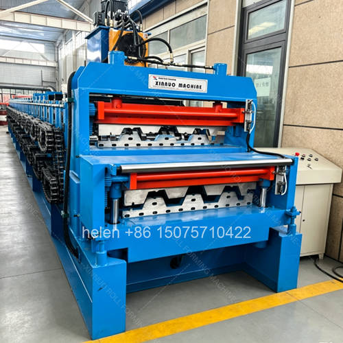
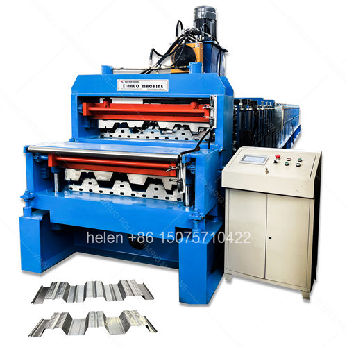
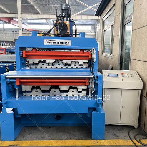
- Stacking a second deck train doubles the product range, not the output
- Each added layer escalates frame, height, weight and commissioning effort
- Deck machines already sit at the top of the standard frame ladder
- That means a second deck layer cannot follow the usual tier step
- Row count and feed width matching become harder with each layer
- Three-layer deck construction is bespoke engineering, not a catalogue option
- The ceiling is set by structure and commissioning, not by demand
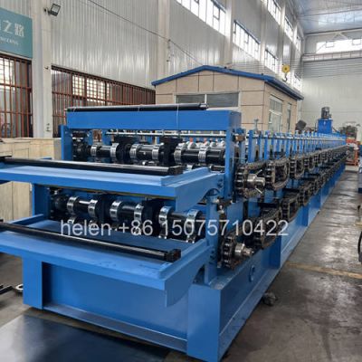
The case for a double layer machine is easy to state: two profiles from one frame, one drive, one foundation, and less factory floor. The case for adding a third layer follows the same logic one step further, and producers who already run two deck profiles sometimes ask whether a third would be better still. The answer depends less on demand than on structure. Each additional layer adds weight and height above the one below it, and the frame has to carry all of them at once.
This page examines how far the stacked-layer principle can be pushed for floor deck profiles specifically. It sets out what each added layer achieves, what it costs structurally, how the frame escalation ladder behaves when the starting point is already a heavy deck machine, how row count and feed width matching compound with more layers, how commissioning effort scales, what changes in drive selection and changeover control, and where the practical ceiling lies. It closes with a decision guide for choosing between one, two, and three layers for a given production profile.
| Configuration | Profiles Available | Footprint Position | Capital Position | Operating Character |
|---|---|---|---|---|
| One layer | One profile | One machine position | Baseline | Full output dedicated to one product at all times |
| Two layers | Two profiles | Materially less than two separate machines, since the second train occupies vertical rather than floor space | Materially less than two separate machines, because one frame, base and control system serve both | One profile at a time, with a changeover of roughly five to fifteen minutes between them |
| Three layers | Three profiles | Less again than three separate machines, but the additional saving per layer diminishes | Less than three separate machines, though the saving per additional layer narrows | Still one profile at a time, but with two changeover paths to manage instead of one |
| Separate machines | One profile each | Highest of all the options | Highest of all the options | All profiles can be produced simultaneously, which no stacked configuration can match |
Note what does not change as layers are added: a stacked machine still produces one profile at a time. Adding a third layer broadens the product range from the same position; it does not add simultaneous capacity. A producer whose constraint is output rather than range gains nothing from a third layer.
| Element | Two Deck Layers | Three Deck Layers |
|---|---|---|
| Machine height | Substantially taller than a single deck line, with service access required above the upper deck | Taller again, typically by several hundred millimetres over the two-layer version, which is where workshop headroom usually becomes the deciding constraint |
| Frame | Escalated from the single deck specification to carry two stacked carriages and their combined vibration | Requires construction beyond the standard frame ladder, since a deck machine already sits at the top of it |
| Mid plate | Increased to carry combined carriage weight and drive torque | Increased further, with the plate dimension becoming a bespoke design decision rather than a catalogue value |
| Shaft | At or near the top of the standard diameter range for deck work | Beyond the standard range, with shaft deflection becoming a governing design criterion for the assembly as a whole |
| Total machine mass | High, concentrated through one base | Higher still, and it is the figure that drives the foundation, the lifting plan and the workshop floor assessment |
| Foundation | Reinforced provision with point loading assessed at the frame feet | Requires engineering assessment, since the concentration of load under one base increases with every layer |
| Lifting and assembly | Significant lifting capacity needed to position the frame | Greater capacity again, and a larger assembly operation on site |
| Access provision | Designed-in platform or steps for the upper deck | Access to a third level, which requires its own provision rather than improvised access |
A single layer machine of any given profile class is normally matched to a frame tier, and adding a second layer escalates the frame one step. That convention works comfortably across the cladding and roofing range, because those machines start low on the ladder and have room to move up. Floor deck does not.
| Starting Point | Single Layer Frame | Two Layers | Three Layers |
|---|---|---|---|
| Light cladding profile | 250 – 300 channel | 300H — one step up, comfortably within the ladder | 350H — still within the ladder with room remaining |
| Standard cladding profile | 300 – 350H | 350H – 400H — one step up | Renewed engineering assessment, near the top of the ladder |
| Floor deck profile | 400H – 450H — already at the top of the standard ladder | 450H is the ceiling. The second deck layer cannot be accommodated by stepping up, so the design must be engineered around the practical limit instead | Beyond the standard ladder entirely. This is a bespoke structural design, not a configuration choice |
That is the central technical fact about stacked deck construction: the usual escalation rule stops working. A two-layer deck machine sits at the top of the conventional frame range, and a three-layer deck machine lies outside it. The practical consequence is that the number of deck layers is limited by structure and by the effort required to commission the assembly, not by the number of profiles a producer would like to offer.
| Constraint | With Two Layers | With Three Layers |
|---|---|---|
| Row count matching | A single pair to reconcile. Identical counts are ideal; a difference of two to four rows is generally acceptable; five to eight rows requires additional motor capability or a revised chain ratio on the slower layer; over ten rows needs engineering assessment. | Three pairs to reconcile simultaneously, and all three layers share one drive speed. The probability that all three fall within the acceptable band is much lower than for two. |
| Feed width matching | Ideally one shared coil width. A difference within roughly 50 mm is handled by guide block adjustment; a larger difference requires separate guiding arrangements. | Three feed widths to reconcile against one decoiler and one entry arrangement. A common width across all three is uncommon, so guide complexity increases. |
| Forming regime consistency | Two regimes sharing one drive. A deck layer and a cladding layer are compatible because the heavier layer governs. | Three regimes, and mixing a deck layer with a decorative pitch-stamped layer alongside a cladding layer introduces three different forming behaviours on one transmission. |
| Error risk at selection | Two possible material paths. Selecting the wrong one is caught quickly on the first panel. | Three possible paths, and the consequence of selecting the wrong deck is more material consumed before the error is noticed. |
| Configuration | Tooling Sets to Align | Typical Commissioning Window | Why It Scales as It Does |
|---|---|---|---|
| Single layer | One | About one day for a standard machine | One set of tooling, one alignment, one first panel to verify. |
| Two layers | Two | Two to three days for a standard double layer | Two sets aligned within one frame, where adjusting one must not disturb the other, and both profiles must be run and measured. |
| Three layers | Three | Substantially longer again, commonly several times the single layer duration | Three sets aligned in one frame with mutual interference between adjustments, three profiles to run, and two changeover paths to verify. The effort is not three times a single layer; it is considerably more. |
| Complex combinations | As applicable | Longest of all | Where layers use different forming regimes, such as deck forming alongside pitch stamping, each regime brings its own setup requirements and its own test criteria. |
| Element | Requirement as Layers Increase |
|---|---|
| Transmission | A single chain arrangement with a selector serving all layers. The chain specification follows the most demanding layer and is escalated above that layer's single machine equivalent. |
| Selector design | Must positively engage the intended layer and clearly indicate which is selected. On a three-layer machine the selector is a more complex mechanism and a correspondingly more critical one. |
| Material path provision | Guide plates and baffles that route material to the intended layer. With three layers there are two alternative paths in addition to the active one, and all must be positively located. |
| Recipe management | Separate stored recipes per layer, so that switching layers does not require manual parameter re-entry. The number of stored recipes grows with the number of layers, and so does the cost of a lost recipe set. |
| Layer selection indication | Explicit indication of the active layer at the control position. Routing material into the wrong train on a heavy deck assembly is a jamming risk with real consequences. |
| Changeover procedure | Documented per transition, since a three-layer machine has more possible transitions than a two-layer one. Every transition should have its own written sequence and its own first panel check. |
| Embedded provision | Anti-pooling devices, embossing arrangements and guides belong to each layer individually. These multiply with the number of layers and cannot be shared between them. |
| Condition | Verdict |
|---|---|
| Two deck profiles, moderate volume for each | Structurally demanding but achievable, and the strongest case for the double layer approach in the deck class. |
| One deck profile plus one cladding profile | Technically the most comfortable deck-based combination, because the deck layer governs the structure and the lighter layer is carried by it. |
| Two deck profiles both running in continuous volume | Two separate machines are the better answer. The one-at-a-time limitation is a real capacity loss that no structural solution removes. |
| Three deck profiles from one machine position | A bespoke engineering proposition beyond the standard frame ladder, requiring structural assessment and a substantially longer commissioning window. |
| Any number of layers where headroom is restricted | The height constraint usually decides the question before the structural one does. Workshop headroom and service access above the top deck must be confirmed first. |
| Any number of layers where floor loading is unverified | Not viable until the foundation and point loading are assessed. The load at the frame feet increases with every stacked layer. |
| Any number of layers where commissioning support is limited | A stacked deck machine does not commission itself. Site cooperation, operator availability, and the buyer's own coil for both or all profiles are prerequisites rather than conveniences. |
| Production Profile | Recommended Configuration | Reasoning |
|---|---|---|
| One profile, high volume | Single layer | A second train adds nothing when the constraint is output on a single product. Buy the machine configured for that profile and that thickness range. |
| Two profiles, one dominant and one periodic | Two layers | The periodic profile is available without a second machine or a second foundation, and changeover cost is incurred rarely. |
| Two profiles, both in genuine volume | Two separate machines | Simultaneous production is worth more than the capital and footprint saving, and redundancy protects delivery commitments. |
| Two deck profiles plus a cladding or roofing profile | Two layers plus interchangeable tooling, or two machines | A third stacked deck layer sits outside the standard frame ladder. Serving the third profile from a separate or tooling-change basis is usually the more practical route. |
| Wide product range, limited space, modest volume per profile | Two or three layers, subject to structure and headroom | This is the scenario the stacked design exists for, subject to the constraints on height, foundation, and commissioning support being satisfied. |
| Wide product range, ample space, volume in every profile | Separate machines | Simultaneous capability across several profiles is worth more than consolidating them into one position. |
| Information | Why It Determines the Answer |
|---|---|
| Drawing for every profile proposed | Working width, overall width, blank width, rib geometry and lap detail for each layer. These drive the tooling and the forming load of each deck. |
| Row count each profile requires | The row matching rule has to be satisfied across all layers, not just one pair. This is usually what decides whether a three-layer proposal is workable. |
| Feed width for every profile | A shared or nearly shared coil width keeps the entry arrangement simple. Divergence multiplies with the number of layers. |
| Thickness range for every profile | The most demanding layer sets the drive and the frame requirement for the whole assembly. |
| Workshop headroom | Stacked height rises with layers. Clearance for the machine and for service access above the top deck is a hard constraint. |
| Floor loading capacity | All layers load one base. Point loading at the feet increases with each added layer and must be assessed rather than assumed. |
| Lifting provision at the machine position | Needed for positioning the frame and for any work on the upper layers. |
| Production volume per profile | Determines how often changeover is incurred, which is the recurring cost of the stacked approach. |
| Changeover frequency expected | Frequent switching between three layers is expensive. Where switching is part of daily routine, simultaneous production from separate machines often wins. |
| Commissioning window and site support | A multi-layer deck machine needs a longer commissioning period, the buyer's coil for every profile, and operators present for each one. |
| Parameter | Standard Range |
|---|---|
| Machine configuration | Two complete deck forming trains stacked vertically in one welded frame sharing one transmission; three-layer construction by bespoke engineering assessment |
| Profile type | Open trapezoidal structural deck and closed re-entrant deck on the deck layer, produced to the buyer's drawings |
| Effective coverage width | 688 – 1025 mm per deck across the standard families; wider by drawing specification |
| Rib height | 39 – 153 mm on the deck layer, depending on profile class |
| Forming rows per deck | 18 – 36 rows on the deck layer, with other layers specified against the row matching rule |
| Frame | 450H welded H-section with 10 mm flange thickness for a two-layer deck machine; beyond the standard ladder for three layers |
| Mid plate | 20 – 25 mm on a two-layer machine; bespoke on a three-layer machine |
| Shaft | Φ95 – 115 mm round bar, rough turned then precision ground; beyond the standard range for three layers |
| Forming wheels | 45# forged steel, quenched to HRC 45 – 50, finish turned, keyed, polished and chrome plated, supplied per deck to its own drawing |
| Embedded provision per deck | Embossing row with clutch arrangement, bearing-mounted oversized rear wheels, reinforcement bars at critical rows, gear drives at high-resistance positions |
| Transmission | 2 inch or 2.5 inch external roller chain with a layer selector, one tier above the deck layer's single machine specification |
| Motor configuration | 2 × 11 kW to 2 × 22 kW on a two-layer machine, set by the deck layer's thickness requirement |
| Feed width | Matched across layers where possible; a difference within roughly 50 mm handled by guide block adjustment |
| Layer changeover | Approximately 5 – 15 minutes to reposition the material path and verify the first panel |
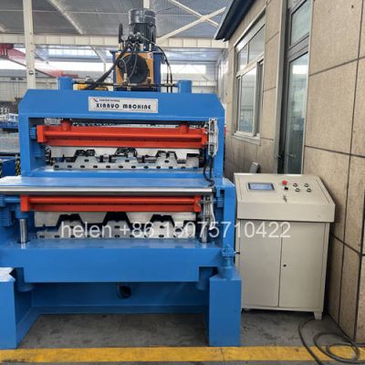
| Shear | Dual-cylinder hydraulic shear at floor level, sized to the heaviest product across all layers, with gravity-assisted discharge |
| Material capability | Deck layer 0.8 – 1.5 mm; other layers to their own profile requirements; galvanized, aluminium-zinc coated and pre-painted coil |
| Forming speed | 8 – 18 m/min on the deck layer, depending on profile depth and material thickness |
| Cut length tolerance | ±1.5 mm |
| Control system | PLC with colour touchscreen HMI, sheet count control, explicit active-layer indication, and a separate stored recipe bank per layer |
| Commissioning | Approximately two to three days for a two-layer deck machine; several times longer for a three-layer assembly |
| Electrical supply | 380 V / 50 Hz / 3-phase standard; alternative voltages and frequencies by destination |
| Certification | CE marking and ISO 9001:2015 compliant manufacturing, with destination-market documentation arranged as required |
Coil loading on the decoiler, strip entry through the guide, selection of the intended roll train at the entry path, progressive forming on the selected deck with embossment at that deck's dimple row, sizing over the final passes, length measurement, dual-cylinder cutting at floor level, and gravity discharge to the stacking position follow the established sequence, with the remaining trains held in the same frame and unaffected by production on the active one.
Hebei Xinnuo is a professional cold roll forming machinery manufacturer with 20+ years of experience. We specialize in C/Z purlin machines, roof panel roll formers, floor deck machines, and custom profile solutions — exported to 50+ countries worldwide.