helen@hbxinnuorollforming.com
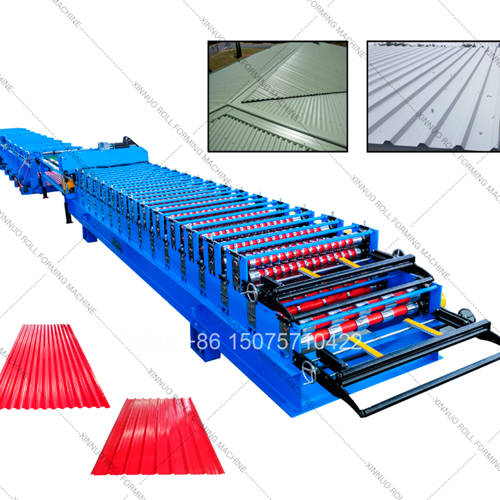
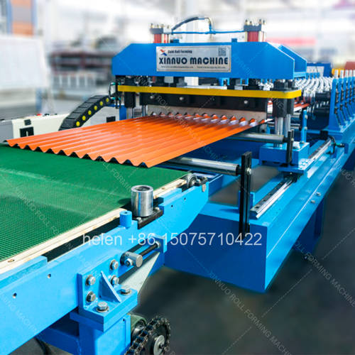
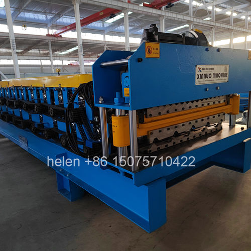
Produces corrugated and IBR metal sheeting from flat steel coil stock
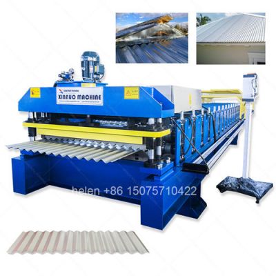
Lower deck forms wave sheeting upper deck forms trapezoidal rib sheeting
Progressive roller stations bend flat strip into finished sheeting profile
PLC digital panel controls sheeting length batch count and line speed
Flying hydraulic shear cuts running sheeting at programmed length on the fly
Hard chrome roller surfaces protect galvanized coating during sheeting process
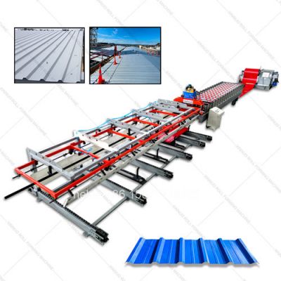
Complete sheeting production line with decoiler shear and discharge conveyor
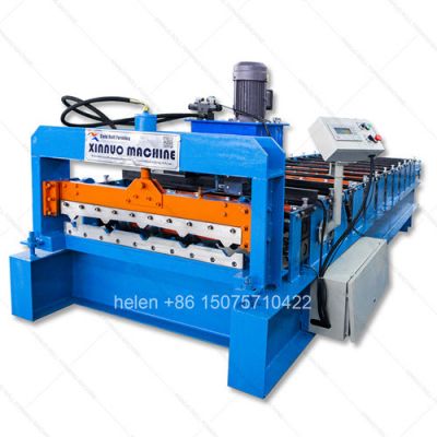
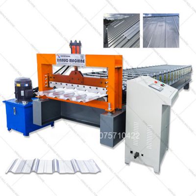
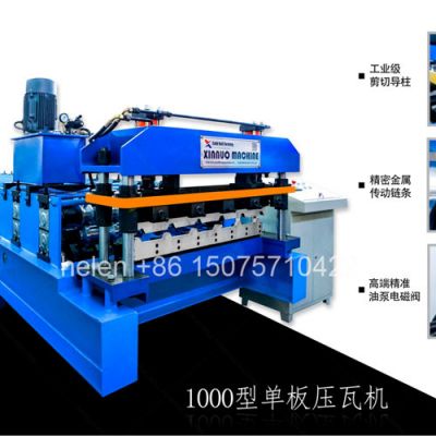
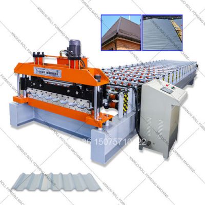
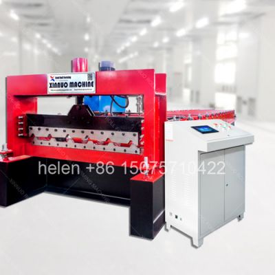
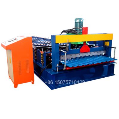
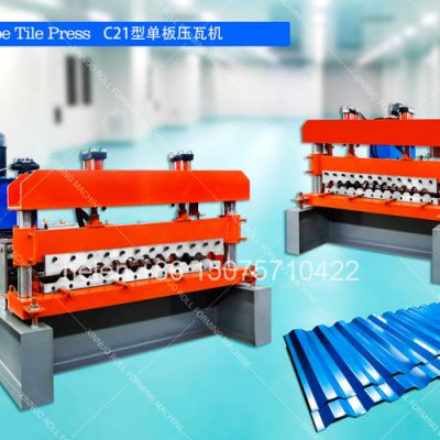
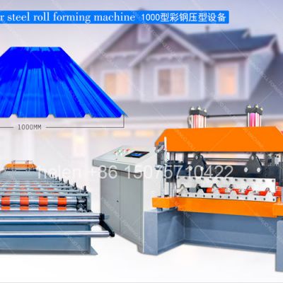
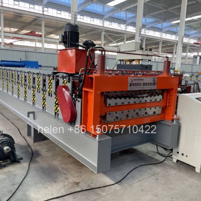
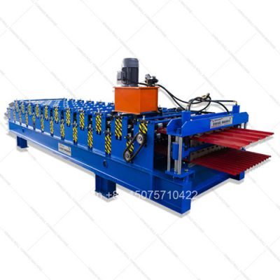
This double layer sheeting machine manufactures two types of metal roofing sheeting from one integrated production station by housing two independent roller forming decks in a single welded structural steel frame. The lower deck produces traditional corrugated wave sheeting — the classic sinusoidal metal roofing profile that has been the foundation material for affordable housing, farm structures, and community buildings across developing markets for generations. The upper deck produces IBR (Inverted Box Rib) trapezoidal sheeting — a deep-rib structural roofing product engineered for long-span industrial warehouses, commercial building envelopes, cyclone-resistant construction, and premium architectural applications. Consolidating both sheeting production capabilities into one machine body allows manufacturers to offer a complete range of metal roofing sheeting products to their construction market without the capital cost, factory floor space, and maintenance overhead of two separate production lines.
| Production Stage | Station Range | Steel Transformation During Sheeting Manufacture |
|---|---|---|
| Strip Reception | Station 1 | Flat steel strip feeds into the first roller pair from the hydraulic decoiler at regulated tension. The entry rollers guide and laterally constrain the strip, establishing the sheeting centerline reference. Edge flange formation initiates as the material enters the sheeting production sequence through the entry guide channel |
| Profile Initiation | Stations 2–5 | Contoured forming rollers apply gentle bending pressure at the exact positions where corrugated wave crests or IBR stiffening ribs will develop. Each station contributes approximately 5–10 degrees of angular deformation. The steel stays within safe forming parameters, preventing zinc coating micro-cracks on galvanized raw coil |
| Progressive Shaping | Stations 6–12 | For corrugated sheeting: wave troughs deepen and crest radii tighten progressively. For IBR sheeting: rib side walls become steeper and valley floor sections flatten under controlled roller pressure. Seven sequential stations distribute total deformation uniformly, achieving even plastic material flow that preserves consistent sheeting gauge thickness across all bent profile zones |
| Final Profile Setting | Stations 13–16 | The last active forming rollers fix the finished sheeting dimensions — wave amplitude and pitch spacing for corrugated output; rib crown height, valley base width, and side lap geometry for IBR output. Roller contours incorporate engineered springback compensation so the produced sheeting maintains its designed cross-section after exiting the forming zone |
| Calibration Verification | Stations 17–18 | A final sizing roller pair performs a quality verification pass to eliminate any residual dimensional variation. At this point the sheeting has attained its complete engineered profile, measured to within ±0.5mm of the specification drawing across the full sheeting cover width |
| Tooling Specification | Corrugated Sheeting Deck | IBR Sheeting Deck |
|---|---|---|
| Roller Station Quantity | 13–16 pairs of upper and lower forming rollers | 14–18 pairs of upper and lower forming rollers |
| Roller Material Source | 45# medium carbon forged steel billet; ultrasonic inspection for internal flaw detection before machining operations begin | 45# medium carbon forged steel billet; ultrasonic inspection for internal flaw detection before machining operations begin |
| CNC Profile Machining | Contour turning with sinusoidal wave form tooling on CNC lathe; profile accuracy maintained within ±0.05mm | Contour turning with trapezoidal rib form tooling on CNC lathe; profile accuracy maintained within ±0.05mm |
| Heat Treatment Method | Controlled-atmosphere gas carburizing furnace processing; oil quench hardening cycle; surface hardness HRC 58–62; impact-tolerant ductile core preserved | Controlled-atmosphere gas carburizing furnace processing; oil quench hardening cycle; surface hardness HRC 58–62; impact-tolerant ductile core preserved |
| Chrome Plating Finish | Industrial hard chrome electrodeposition process; 0.05mm minimum deposit thickness; mirror-grade polished surface for friction-free sheeting production | Industrial hard chrome electrodeposition process; 0.05mm minimum deposit thickness; mirror-grade polished surface for friction-free sheeting production |
| Drive Shaft Engineering | Φ75–Φ80mm 40Cr alloy steel bar stock; precision ground to h7 tolerance class; keyway slot machined for drive sprocket attachment | Φ75–Φ80mm 40Cr alloy steel bar stock; precision ground to h7 tolerance class; keyway slot machined for drive sprocket attachment |
| Bearing Support System | Split cast iron pillow block housing; double-row self-aligning spherical roller bearing element; Zerk-type grease fitting lubrication access | Split cast iron pillow block housing; double-row self-aligning spherical roller bearing element; Zerk-type grease fitting lubrication access |
| Output Parameter | Corrugated Sheeting | IBR Sheeting |
|---|---|---|
| Effective Cover Width | 660mm to 1000mm coverage per sheet | 762mm to 1100mm coverage per sheet |
| Profile Height | 12–18mm wave amplitude crest-to-trough | 28–43mm rib crown elevation above valley plane |
| Waves or Ribs per Sheet | 5, 7, 9, or 11 sinusoidal wave cycles | 4, 5, or 6 trapezoidal stiffening ribs |
| Sheeting Length Range | 1.0m minimum to 14.0m maximum per piece | 1.0m minimum to 14.0m maximum per piece |
| Side Lap Configuration | 1.5-wave minimum overlap for weathertight longitudinal joint seal | Single overlap with optional anti-capillary groove for water-blocking side lap seal |
| Coil Feed Width Required | 914–1220mm flat strip before sheeting process | 1000–1250mm flat strip before sheeting process |
| Machine System | Engineering and Construction Detail |
|---|---|
| Welded Structural Frame | Heavy-gauge channel steel longitudinal members with cross-braced H-beam vertical support columns fabricated from 300H–400H structural grade steel. The complete welded chassis undergoes post-fabrication thermal stress-relief annealing in an industrial furnace to neutralize all residual fabrication stresses. Following heat treatment, every bearing housing mounting surface is precision machined flat to guarantee absolute shaft axis parallelism through all roller stations in both sheeting production decks |
| Drive Motor and Gearbox | 5.5kW or 7.5kW AC induction motor (4-pole design, 1440 rpm rated output speed, IP54 enclosure protection rating) directly coupled to a worm-type dual-output shaft speed reduction gearbox with oil-bath gear lubrication. Available reduction ratios: 1:40 for higher-speed sheeting production using thinner gauge coil or 1:59 for higher-torque sheeting production using heavier gauge coil. Each gearbox output shaft independently drives one complete sheeting deck through a dedicated heavy-duty double-row industrial roller chain transmission circuit with hardened alloy steel sprockets on every roller shaft and individual chain tension adjustment per loop |
| Hydraulic Cutting Assembly | 4.0kW gear-type hydraulic pump motor supplying a complete 80-liter oil reservoir system equipped with inline return filtration, breather cap vent, sight glass oil level indicator, and oil operating temperature monitor. The flying shear carriage assembly operates on precision linear guide rails and incorporates a pneumatic sheeting clamp mechanism. The Cr12MoV cold-work die steel blade set receives vacuum heat treatment to HRC 60–64 and is profile-ground to precisely match the sheeting cross-section for producing clean, burr-free cuts that fully preserve the formed sheeting profile geometry without any deformation |
| PLC Digital Control System | Programmable logic controller central processor (customer-selectable brand: Siemens S7-1200 series, Delta DVP series, or Mitsubishi FX3U series) paired with a variable frequency drive inverter module providing stepless sheeting production speed regulation capability. Human-machine interface: 7-inch or 10-inch color LCD touchscreen HMI operator panel with multi-language display support and programmable product recipe storage memory. Real-time sheeting length measurement is accomplished via a rotary pulse encoder mounted on the final forming shaft with continuous digital feedback signal transmission to the PLC auto-correction logic algorithm. Comprehensive safety infrastructure includes mechanical limit switches for shear carriage home position and over-travel detection plus three emergency stop mushroom-head pushbutton stations strategically located along the sheeting production line at the operator control position, hydraulic shear station, and finished sheeting discharge area |
| No. | Line Component | Function in Sheeting Production |
|---|---|---|
| 1 | Hydraulic Mandrel Uncoiler | Holds the raw steel coil on hydraulically expanding jaw elements rated for 5-ton or 8-ton coil weight capacity. Adjustable pneumatic or mechanical disc brake system maintains consistent strip pay-off tension ensuring uniform sheeting quality from the first meter to the last meter of every coil processed |
| 2 | Entry Guide and Pre-Shear Station | Adjustable-width side guide roller rails center the incoming strip precisely on the sheeting machine centerline axis. An integrated manual guillotine blade squares the coil leading edge before the strip is threaded into the selected roller deck entrance for sheeting production commencement |
| 3 | Double Layer Main Sheeting Unit | Central sheeting production station integrating the lower corrugated sheeting roller deck and upper IBR sheeting roller deck within a single welded structural frame. A pivoting material diverter plate at the machine entry directs the incoming strip into whichever deck is active. Both sheeting decks share a common drive motor, dual-output speed reduction gearbox, chain drive transmission circuits, hydraulic post-cut shear, and PLC digital control system |
| 4 | Flying Hydraulic Post-Cut Shear | Upon receiving the cut trigger command signal from the PLC controller, the shear carriage assembly accelerates to synchronize its speed with the sheeting production line speed. A pneumatic sheeting clamp secures the formed sheeting, the hydraulic actuating cylinder drives the profiled cutting blade through the complete sheeting cross-section, then both blade assembly and carriage retract to the home reference position — the entire cut-and-return operating cycle is executed seamlessly without interrupting the continuous sheeting production flow |
| 5 | Digital Electrical Control Enclosure | IP54 weather-resistant steel cabinet housing the PLC central processing unit, VFD inverter module, motor contactors, thermal overload protection relays, circuit breakers, and electrical terminal connection blocks. The color touchscreen HMI operator interface panel is externally mounted for convenient operator access to sheeting length value programming, production batch quantity setting, sheeting production speed adjustment, and equipment fault condition diagnostic display |
| 6 | Sheeting Discharge Roller Conveyor | 3m–5m free-roller receiving table with height-adjustable support legs. Collects finished cut sheeting as it exits the hydraulic shear station and provides a stable ergonomic work platform for manual sheeting collection, stacking into product bundles, steel strapping, and transport to the finished goods warehouse storage area |
| Specification Item | Technical Data |
|---|---|
| Compatible Coil Material Types | Hot-dip galvanized steel coil (zinc coating mass Z60–Z275 g/m² range), pre-painted galvanized iron coil (PPGI with polyester, SMP, or PVDF paint topcoat system), aluzinc/Galvalume coated steel coil (AZ150–AZ200 specification), cold-rolled steel strip, aluminum alloy sheeting coil (grade 1100 and 3003 series) |
| Sheeting Material Thickness Range | 0.25mm to 0.80mm (equivalent to gauge 30 through gauge 20) |
| Material Yield Strength Capability | 200 MPa up to 400 MPa covering mild steel grades through high-tensile structural steel grades |
| Sheeting Production Line Speed | 10–18 linear meters of finished sheeting per minute; infinitely variable speed adjustment through the VFD inverter digital control interface |
| Sheeting Cut Length Precision | ±1.0mm at any operator-programmed sheeting length via rotary encoder real-time digital pulse feedback signal to the PLC auto-correction control algorithm |
| Sheeting Type Changeover Procedure | Manual pivoting material diverter plate repositioning operation; switching from corrugated sheeting production to IBR sheeting production completed in approximately 10–15 minutes including the strip re-threading procedure through the alternate roller deck |
| Electrical Power Supply | 380V 50Hz 3-phase standard factory configuration; custom voltage options (220V, 415V, 440V, 480V) and frequency (50Hz or 60Hz) configured to match the destination country electrical utility grid specifications |
| Total Connected Motor Power Rating | Approximately 10–12 kW combined total (main drive motor 5.5/7.5kW + hydraulic pump drive motor 4.0kW) |
| Machine Overall Dimensions | Approximately L 7.0–8.0m × W 1.4–1.6m × H 1.7–2.0m; final machine dimensions determined by the ordered roller station quantity and frame structural specification grade |
| Machine Net Shipping Weight | 5.0 to 7.5 metric tons depending on the selected profile configuration, roller station count, and frame structural grade specification |
| Uncoiler Coil Weight Rating | 5 metric tons standard duty rating or 8 metric tons heavy duty rating per customer daily sheeting production throughput requirement |
| Coil Inner Bore Diameter | Φ508mm industry standard bore diameter; Φ610mm bore diameter available with uncoiler mandrel adapter sleeve upon customer request |
| Step | Workflow Stage | Operational Description |
|---|---|---|
| 1 | Coil Installation | Raw steel coil positioned onto the hydraulic uncoiler expanding mandrel using overhead crane or coil loading cart equipment. Hydraulic expansion jaws engage and securely lock the coil inner bore diameter. Brake resistance setting adjusted to deliver uniform strip feed tension throughout the complete sheeting production run for consistent product quality output |
| 2 | Strip Alignment | Coil leading edge guided through the adjustable entry side roller alignment assembly to achieve precise centerline positioning on the sheeting machine axis. The manual guillotine pre-shear blade squares the coil head before the strip enters the selected roller deck entrance point for sheeting production start-up |
| 3 | Deck Selection | Operator positions the pivoting material diverter guide plate — downward orientation routes the strip into the lower corrugated sheeting production deck; upward orientation routes into the upper IBR sheeting production deck. Changing from one sheeting product type to the other requires approximately 10 minutes for diverter repositioning and strip re-threading through the alternate deck |
| 4 | Progressive Roll Forming | The flat steel strip advances sequentially through each roller station pair in order; at every station the metal receives controlled incremental bending deformation until, emerging from the final forming station, the strip has been completely transformed into finished corrugated wave sheeting or complete IBR trapezoidal profile sheeting ready for cutting to the programmed length specification |
| 5 | Length Measurement Tracking | Rotary pulse encoder mounted on the final drive shaft transmits continuous digital pulse signals to the PLC central processor; the controller compares the real-time accumulated pulse count total against the operator-entered target sheeting length value displayed on the touchscreen HMI panel |
| 6 | Automatic Sheeting Cut | When the target sheeting length is reached the PLC initiates the automated cutting sequence: pneumatic sheeting clamp engages and secures the formed sheeting → shear carriage accelerates to synchronize with the sheeting production line speed → hydraulic cylinder drives the profiled Cr12MoV blade through the complete sheeting cross-section → blade assembly retracts and carriage returns to the home reference position — the entire cut cycle is executed without stopping or reducing the sheeting production speed |
| 7 | Sheeting Collection | The separated finished sheeting slides onto the free-roller discharge conveyor table surface; the operator lifts each completed sheeting piece and stacks it onto the product pallet or sheeting bundle for steel strapping, finished goods inventory warehousing, and delivery to building material distributors or construction project sites |
| Cost Analysis Factor | Two Independent Sheeting Production Lines | One Double Layer Sheeting Production Line |
|---|---|---|
| Equipment Investment Cost | 100% baseline — total purchase price of two complete sheeting machines plus two uncoilers | Approximately 65–75% of the combined two-machine total expenditure |
| Factory Floor Space Consumption | 44–70 square meters occupied by both sheeting production lines | 20–35 square meters for the single dual-output sheeting production line |
| Ocean Container Freight Cost | Two 20GP shipping containers, two separate ocean freight invoices | One 20GP or 40HQ shipping container, single consolidated ocean freight invoice |
| Foundation and Utility Infrastructure | Two concrete machine foundation pads, two electrical power supply drops, two cable installation runs | Single concrete machine foundation pad, one electrical power supply drop, one cable installation run |
| Production Workforce per Shift | 3–4 operators required across two independent sheeting production lines | 1–2 operators sufficient for one dual-deck sheeting production line per shift |
| Monthly Electricity Operating Cost | Two drive motors and two hydraulic pump motors drawing power simultaneously | Single drive motor and single hydraulic pump motor operating — approximately 40% reduction in monthly electricity consumption |
| Spare Wearing Parts Stock | Two complete sets of wearing components held in warehouse spare parts inventory | One spare parts kit services both sheeting production roller decks |
Before export crating authorization, every completed sheeting machine must successfully pass a rigorous three-phase factory quality verification protocol. Phase one — comprehensive dimensional inspection: all roller gaps at every forming station are measured using calibrated feeler gauges and cross-checked against the engineering tolerance specification table; shaft concentricity runout is verified at every bearing position with dial test indicator instruments; frame structural alignment and squareness are confirmed using precision spirit levels and cross-laser measurement instrumentation. Phase two — extended no-load operational endurance testing: the machine operates continuously at maximum rated sheeting production speed without material for a minimum duration of four hours; bearing housing temperatures are monitored and recorded at 30-minute intervals using infrared non-contact thermometers; chain drive sprocket tooth engagement is inspected both visually and audibly for smooth, uniform meshing characteristics; every PLC control function undergoes complete operational validation testing including power-up sequencing, motor start and stop cycling, sheeting production speed regulation, sheeting length value programming, production batch quantity setting, product recipe storage and recall, emergency stop circuit activation, and full system restart — confirming total control system integration and fault-free operational capability. Phase three — live sheeting production validation trial: factory technicians load genuine galvanized steel coil raw material stock and produce 50 consecutive corrugated sheeting pieces plus 50 consecutive IBR sheeting pieces under actual production operating conditions; every 10th produced sheeting piece is measured for finished length, wave pitch spacing or rib profile geometry, and cut edge quality using calibrated digital measuring instruments. Only machines achieving zero out-of-tolerance measurement results across all three inspection phases receive final approval for export protective packaging and container loading authorization.
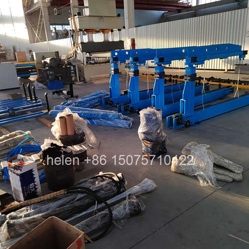
The main sheeting machine body receives comprehensive multi-layer protective export packaging engineered specifically for ocean freight transit conditions: an inner wrap layer of VCI (volatile corrosion inhibitor) anti-rust protective film; a middle layer of high-density closed-cell foam padding applied to all corners, machined surfaces, and protruding mechanical components; an outer wrap layer of heavy-gauge UV-stabilized polyethylene shrink film providing moisture ingress protection, dust contamination prevention, and mechanical handling damage resistance during ocean transit. The fully wrapped assembly is securely bolted through its base frame structure to a fumigated ISPM-15 certified plywood pallet or welded structural steel export skid. The hydraulic uncoiler unit, sheeting discharge roller conveyor table, hydraulic power pack assembly, and digital electrical control enclosure are each packed individually in purpose-built marked fumigated wooden crates with internal closed-cell foam bracing and bolted steel tie-downs for secure ocean freight transit protection. A dedicated accessories crate contains the operator hand tool kit, starter set of spare wearing parts, and one complete printed set of technical documentation: mechanical assembly engineering drawings with exploded component identification views, electrical wiring schematic diagram with terminal block and wire number labeling, PLC parameter programming and configuration reference guide, daily and weekly lubrication maintenance schedule chart with recommended grease type specifications, and the comprehensive English-language operation and maintenance instruction manual. Standard factory manufacturing lead time is 25–35 working days from confirmed deposit payment receipt and customer-signed profile approval engineering drawings. Standard warranty coverage is 12 months from the ocean bill of lading date against defects in materials and factory workmanship quality.
| Optional Enhancement | Description and Operational Advantage |
|---|---|
| Servo Motor Drive System Conversion | Replace the standard AC induction drive motor with a programmable precision servo motor drive system for controlled sheeting production acceleration and deceleration motion profiles, enhanced finished sheeting length accuracy, and reduced electrical energy consumption during intermittent sheeting production cycle operation |
| Automatic Sheeting Stacking Mechanism | Motorized stacking arm assembly that transfers finished produced sheeting from the discharge roller conveyor table to neatly aligned product bundles positioned on a waiting pallet, completely eliminating manual sheeting handling labor requirements and substantially reducing operator physical fatigue during extended production shift operations |
| Electric Coil Transport Trolley | Battery-electric powered cart operating on floor-mounted steel guide rails with integrated hydraulic scissor lift platform mechanism; safely transports raw steel coils weighing up to 10 metric tons from warehouse coil storage directly to the uncoiler expanding mandrel without requiring overhead crane equipment availability in the sheeting production facility |
| IoT Remote Monitoring System | 4G cellular network-connected module that transmits real-time sheeting production performance metrics — daily finished sheeting output tally count, motor operating hours accumulation, equipment fault diagnostic trouble codes, and scheduled preventive maintenance interval reminder notifications — to a dedicated smartphone mobile application or web-based production management dashboard interface for remote factory oversight |
| Custom Embossing Roller Station | Specially engraved forming roller pair integrated into the sheeting production roller sequence that permanently imprints a manufacturer brand name, company identification logo, or production date batch code into each sheeting piece during the production process for product traceability identification and market brand recognition purposes |
| Stainless Steel Roller Tooling Option | Complete sheeting production roller set manufactured from grade 304 or 316L austenitic stainless steel material for sheeting production operations in food-grade processing facilities, pharmaceutical manufacturing plants, chemical industry production environments, or high-atmospheric-salinity coastal production locations where standard carbon steel rollers would be vulnerable to accelerated corrosion degradation over time |
Hebei Xinnuo is a professional cold roll forming machinery manufacturer with 20+ years of experience. We specialize in C/Z purlin machines, roof panel roll formers, floor deck machines, and custom profile solutions — exported to 50+ countries worldwide.