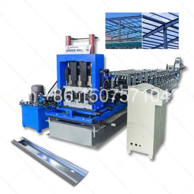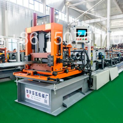
helen@hbxinnuorollforming.com
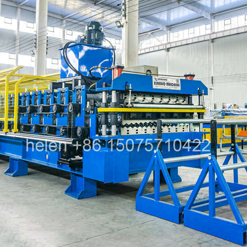
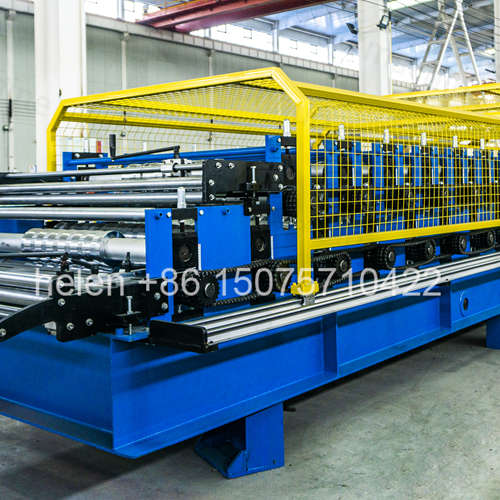
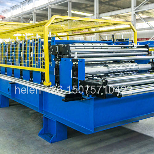
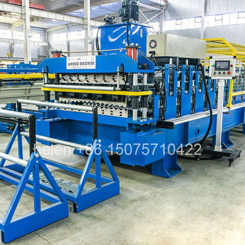
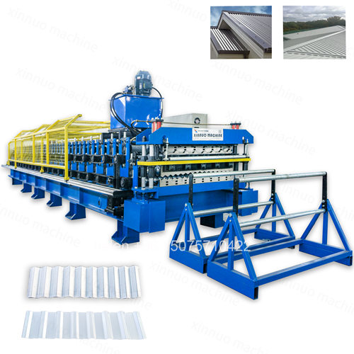
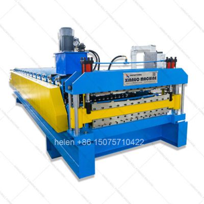
- Two complete roller forming tiers stacked within one welded steel chassis
- Selectable profile pairs span trapezoidal IBR corrugated glazed tile and arc wave
- Frame grade escalates with combined carriage weight and profile rib depth
- Row count matching between tiers prevents speed divergence and profile defects
- Feed width matching lets both tiers share a single decoiler and coil stock
- PLC stores independent length batch and speed recipes for each forming tier
- Changeover between tiers completes in minutes without roller or die replacement
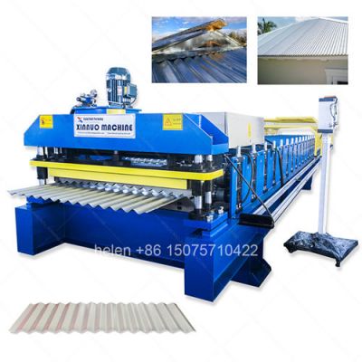
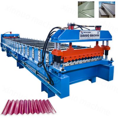
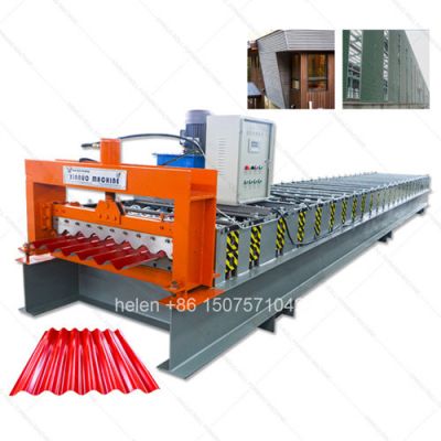
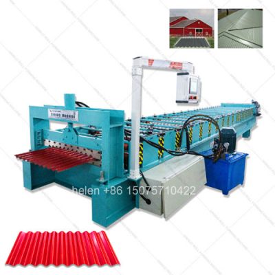
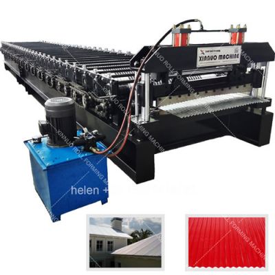
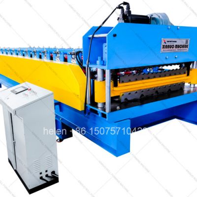
A double layer roll forming machine is defined by a single engineering principle: two complete sets of forming rollers mounted one above the other inside a common structural frame, sharing one drive motor, one hydraulic cutting station, and one control system. Material is routed into either the upper or the lower roller set by adjusting the entry guide path — a change that requires no tooling removal, no roller substitution, and no mechanical reconfiguration. The machine produces one profile at a time, but it holds two profiles in permanent readiness.
What separates a well-engineered double layer machine from a poorly engineered one is not the concept — it is the execution of four interlocking design decisions: frame rigidity under stacked load, row-count balance between the two tiers, feed-width compatibility, and drive train sizing. Each decision propagates through the entire machine, and a compromise in any one of them surfaces years later as profile drift, premature bearing failure, or a second tier that never reaches acceptable production quality. The following sections present these decision rules in the form of a selection framework, so buyers can evaluate any double layer machine quotation against objective engineering criteria rather than price alone.
Double layer machines are not a single product. They are a product family organized by which two profile types are paired. The pairing determines the roller tooling cost, the commissioning difficulty, the drive sizing, and ultimately the market the machine can serve. The table below maps the recognized combination families to their commercial characteristics.
| Type | Profile Pairing | Tooling Cost | Commissioning | Relative Price | Commercial Rationale and Target Buyer |
|---|---|---|---|---|---|
| A | Trapezoidal + Trapezoidal (two widths) | Lowest | Easiest — 2 days | 100 (baseline) | Both tiers share the same forming principle. Lowest engineering risk. Buyer serves different building scales within one profile family, or exports to two countries with different national width standards. |
| B | Trapezoidal + Glazed Tile | Moderate | Hard — 3-5 days | 112-120 | Highest-volume mixed pairing. IBR tier serves industrial and commercial buyers; glazed tile tier serves premium residential and heritage projects. Requires pitch-stamping mechanism on the tile tier. |
| C | Arc Wave + Trapezoidal | Moderate | Moderate — 3 days | 110-118 | Both tiers are continuous roll-formed, so no intermittent stamping complexity. Covers the two most common industrial roofing profiles in developing markets. Highest export volume combination in the arc family. |
| D | Arc Wave + Glazed Tile | Highest | Hardest — 4-6 days | 125-135 | Combines a continuous roller tier with an intermittent stamping tier — the two most different forming principles in one frame. Buyers serve industrial roofing plus decorative heritage architecture in the same regional market. |
| E | Arc Wave + Arc Wave (two wave specifications) | Low-Moderate | Moderate — 3 days | 105-112 | Rare but technically straightforward. Feasible only when wave height difference between the two tiers stays within approximately 15 mm, otherwise the carriage height differential complicates frame design. |
| F | Triple Layer (three tiers) | Highest | Longest — 5-8 days | 55-65% of three single machines | Not a double layer machine in the strict sense, but part of the same stacked-architecture family. Three profiles in one frame. Suited to showrooms, distribution centers, and multi-market export operations. |
| G | Forming + Slitting Composite | Custom | Custom | Quotation-based | One tier forms roofing profiles while the other tier slits coil into narrower strips for downstream processing. Suited to manufacturers who both form and supply cut-to-width coil. |
The main frame must carry the static weight of two roller carriages plus the dynamic forming loads and vibration generated during production. As a rule, the double layer frame requires one grade higher than the heavier of the two equivalent single-layer machines. Selecting a lighter frame to reduce cost is the single most common cause of long-term profile drift in double layer machines, because micro-deflection accumulates and permanently misaligns the roller gap.
| Equivalent Single-Layer Frame | Required Double Layer Frame | Combined Machine Weight Range | Engineering Reason for the Escalation |
|---|---|---|---|
| 250 channel steel | 300H H-section | Approximately 4.5-6.0 t | Stacked carriage weight alone exceeds the deflection tolerance of channel steel side plates |
| 300H H-section | 350H H-section | Approximately 6.0-7.5 t | Vibration from two carriages superimposes; 350H maintains roller alignment under combined dynamic load |
| 350H H-section | 400H H-section | Approximately 7.5-9.0 t | Deep-rib or wide-width profiles on the heavier tier require greater torsional rigidity across the frame span |
| 400H H-section | 450H H-section | Approximately 9.0-14.0 t | Reserved for wide arc profiles with high peak counts, or triple-layer architecture with three stacked carriages |
Two tiers sharing one drive motor and one line speed must be matched in two dimensions. Mismatch in either dimension manifests as a specific, predictable defect — which is why these two rules are the most frequently violated in low-cost machine quotations.
| Matching Dimension | Ideal Condition | Consequence of Mismatch | Corrective Engineering Measure |
|---|---|---|---|
| Roller Row Count | Difference of 0-4 rows between tiers | The tier with fewer rows forms incompletely and produces profile defects; the two tiers' roller diameters differ, causing linear speed divergence at the same shaft RPM and unstable material travel | Increase motor power on the slower tier, or adjust the chain ratio so both tiers present equivalent surface speed to the strip |
| Roller Row Count (extreme case) | Avoid differences exceeding 10 rows | Speed divergence becomes severe; the strip alternately tensions and slackens, producing waviness and inconsistent rib height along the sheet length | Requires formal engineering evaluation before order confirmation — not resolvable by field adjustment |
| Feed / Coil Width | Identical width on both tiers | Shared decoiler and entry frame cannot serve both tiers; requires two separate guiding systems and manual adjustment at every switchover | Select profile pairs with matching feed width where possible — this is the single highest-value selection decision for simplifying daily operation |
| Feed / Coil Width (near match) | Difference within 50 mm | Minor lateral misalignment at the entry of one tier | Adjustable guide blocks compensate — acceptable and common in practice |
Double layer machine demand is not uniform across geographies. Buyers in different regions face different national profile standards, different construction mixes, and different competitive landscapes. The pairing that sells best in one country may be commercially wrong in another. The table below summarizes how pairing preference varies by market region.
| Region | Dominant Pairing | Market Condition Driving the Pairing | Buyer Motivation for Choosing Double Layer Over Single |
|---|---|---|---|
| Southern Africa | IBR + IBR (two widths) | Mature IBR market with strong national width standards; residential and industrial both served by IBR-type profiles | Serve residential and industrial project scales from one machine; avoid capital outlay on two dedicated machines in a price-competitive market |
| East & West Africa | IBR + Corrugated | Urban commercial construction demands IBR while rural and mass housing still relies on corrugated sheeting | Cover both the urban premium segment and the rural volume segment without choosing between them at the point of purchase |
| Middle East / GCC | IBR + Corrugated or Arc + Trapezoidal | Mega-project industrial roofing plus large hospitality and residential programs | Wide profiles for large-span structures paired with a second high-demand profile; equipment cost is secondary to delivery reliability and capacity |
| Southeast Asia | Trapezoidal + Glazed Tile | Strong traditional clay tile aesthetic in residential architecture alongside rapid industrial park development | Capture premium decorative residential pricing while maintaining an industrial-commercial product line |
| Central & South Asia | Arc Wave + Trapezoidal | Industrial roofing standard uses arc/corrugated wave; commercial and institutional buildings increasingly specify trapezoidal | Covers the two profiles most frequently requested in tender specifications from a single asset |
| Latin America | Corrugated + Trapezoidal | Mining and industrial infrastructure drives corrugated demand; commercial construction drives trapezoidal | Feed-width-matched pairs reduce coil inventory complexity across both product lines |
A double layer machine is not universally superior to two single machines. It is superior under specific operating conditions and inferior under others. Honest selection requires matching the machine architecture to the actual production model the buyer intends to run.
| Operating Condition | Double Layer Machine Is the Correct Choice | Two Single Machines Are the Correct Choice |
|---|---|---|
| Order pattern | Orders alternate between the two profiles; rarely need both simultaneously | Both profiles must be produced simultaneously and continuously to meet standing demand |
| Available capital | Capital constrained; cannot fund two complete production lines without delaying other investments | Capital available; marginal savings from combining are not material to the business |
| Factory floor area | Limited; two machine footprints plus access aisles will not fit the current building | Ample space; footprint is not a constraining factor |
| Labor availability | One trained operator is the realistic staffing level | Two operators can be staffed and supervised effectively |
| Maintenance capability | Simple, consolidated maintenance routine is preferred; spare parts inventory should stay minimal | Dedicated maintenance capability exists and two separate maintenance schedules can be managed |
| Product mix stability | Product mix changes over time or varies by season; flexibility has higher value than peak throughput | Product mix is stable and known; peak throughput on both profiles has higher value than flexibility |
| Entry into a new market | Testing demand for a second profile before committing to dedicated capacity | Demand for both profiles is already proven and understood |
| Parameter | Standard Configuration and Available Options |
|---|---|
| Machine Architecture | Two roller tiers mounted vertically in one structural frame, sharing one drive motor via selector clutch, one hydraulic shear, and one PLC control system |
| Available Pairings | Trapezoidal+trapezoidal, trapezoidal+glazed tile, arc+trapezoidal, arc+glazed tile, arc+arc, triple layer, and forming+slitting composite (quotation-based) |
| Main Frame Grades | 300H, 350H, 400H, or 450H welded H-section steel — selected per combined carriage load and profile rib depth |
| Side Panel Thickness | 16 mm to 20 mm CNC laser-cut steel plate with precision-machined bearing seat bores |
| Typical Tier A Roller Rows | 12 to 18 rows depending on profile type; trapezoidal and deep-rib profiles use more rows than shallow corrugated |
| Typical Tier B Roller Rows | 11 to 18 rows; row count difference between tiers should stay within 0-4 rows for optimal forming balance |
| Roller Material | 45# forged carbon steel, CNC contour-turned, surface-ground, industrial hard chrome plated to HRC 58-62 |
| Roller Shaft | Φ75 mm or Φ80 mm solid steel, centerless ground, dual-row self-aligning spherical roller bearings |
| Drive Transmission | Duplex roller chain — 6-fen (3/4 in) pitch standard or 1 in pitch heavy-duty, with hardened sprockets and adjustable idler tensioners |
| Chain Sizing Rule | Sized on the higher-torque tier, typically one grade above the equivalent single-layer machine of the heavier profile |
| Main Motor Power | 5.5 kW, 7.5 kW, or 11 kW depending on frame grade and profile forming load; VFD-controlled stepless speed adjustment |
| Forming Speed | 8 to 20 m/min; effective ceiling set by the lower-speed tier when a glazed tile pitch-stamping tier is fitted |
| Material Thickness | 0.30 mm to 0.80 mm standard; up to 1.00 mm with reinforced frame and upgraded motor upon engineering confirmation |
| Coil Material Types | PPGI, PPGL, HDGI galvanized, aluminium-zinc coated coil, and pre-painted aluminium sheet |
| Coil Width Capability | Up to 1250 mm per tier, depending on target effective width and profile geometry |
| Hydraulic Cutting Station | Guillotine or post-cut flying shear with Cr12MoV blades, HRC 60-62, independent 4.0 kW hydraulic power pack |
| Cut Length Accuracy | ±1.5 mm verified by rotary encoder closed-loop measurement; tighter tolerance available on request with upgraded measurement system |
| Control System | PLC with 7 in colour touchscreen HMI; independent recipe banks for each tier; fault diagnostics display; multi-language interface |
| Recipe Storage | Up to 50 production recipes per tier — each storing sheet length, batch quantity, and forming speed |
| Changeover Procedure | Adjust entry diverter guide to the target tier, verify strip centring on side guides, select the target recipe on the HMI |
| Changeover Duration | Approximately 5 to 15 minutes for continuous-roller pairings; longer where an intermittent pitch-stamping tier is involved |
| Commissioning Duration | Approximately 2 days (trapezoidal pairings) to 8 days (triple layer), with mixed-principle pairings requiring the longest calibration |
| Electrical Standard | 380 V / 50 Hz / 3-phase standard; customisable to 220 V, 440 V, or 480 V at 50 or 60 Hz by destination country |
| Occupied Floor Area | Approximately 20 to 40 m² depending on frame grade, row count, and total line length including decoiler and run-out table |
| Frame Height Increase | Approximately 300 to 500 mm taller than the equivalent single-layer machine; triple layer configurations add further height |
| Machine Weight Range | Approximately 4.5 t (light trapezoidal pairing) to 14 t (wide arc profile or triple layer configuration) |
| Quality Certification | CE marking and ISO 9001:2015 compliant manufacturing process |
| Resource Dimension | Two Single Machines | One Double Layer Machine | One Triple Layer Machine |
|---|---|---|---|
| Number of profiles available | 2 | 2 | 3 |
| Relative equipment cost | 100 (baseline) | 65-75 | 55-65 of a three-machine baseline |
| Relative floor space | 100 (baseline) | 40-60 | 35-50 of a three-machine baseline |
| Operators required | 2 for simultaneous production | 1 (sequential production) | 1 (sequential production) |
| Simultaneous output capability | Yes | No — one tier active at a time | No — one tier active at a time |
| Commissioning time | 1 day per machine | 2-5 days | 5-8 days |
| Changeover mechanism | Move material to the other machine | Divert material path — no tooling change | Divert material path across three positions |
| Maintenance scope | Two independent schedules | One consolidated schedule | One consolidated schedule, three tiers |
| Spare parts inventory | Two sets of wear components | One set, dual-purpose | One set, triple-purpose |
| Best-fit business model | Continuous simultaneous high-volume output of both profiles | Batch production following order demand across two profiles | Multi-market or showroom operation across three profiles |
Because two forming tiers share one drive train and one frame, verification must cover each tier independently and the interaction between them. The following checks form a practical acceptance protocol for buyers receiving a double layer machine.
| # | Verification Item | Acceptance Basis |
|---|---|---|
| 1 | Frame squareness and level | Diagonal and level measurement across the frame before commissioning — establishes the reference geometry for both tiers |
| 2 | Tier A profile geometry | Produce a minimum of 10 sheets; measure rib height, rib pitch, effective width, and sheet straightness against the approved profile drawing |
| 3 | Tier B profile geometry | Repeat the same measurement set on the second tier; confirm both tiers independently meet drawing tolerance |
| 4 | Coating surface integrity | Inspect formed sheets from both tiers under raking light for scratches, rub marks, or coating transfer — critical where pre-painted coil is used |
| 5 | Cut length repeatability | Cut multiple sheets at three different programmed lengths on each tier; verify measured length against the programmed value |
| 6 | Changeover repeatability | Switch between tiers at least twice and confirm the first sheet produced after each switchover meets full specification without re-calibration |
| 7 | Chain tension balance across tiers | Check tension at each selector position; unequal tension indicates a drive configuration that will cause speed divergence over time |
| 8 | Hydraulic cutting performance | Confirm clean, square, burr-free cuts without coating delamination at the cut edge on both tiers |
| 9 | Control system independence | Verify each tier's recipe bank stores and recalls its own length, quantity, and speed parameters without affecting the other tier |
| 10 | Thermal stability under sustained run | Run both tiers through extended production and monitor bearing and gearbox temperature rise to confirm the frame and drive are not overloaded |
A double layer machine typically serves a longer operational life than a single-layer machine of the same duty, because daily production is distributed across two roller carriages rather than concentrated on one. However, this benefit only materializes if the shared components — the main frame, the drive train, and the hydraulic cutting station — are sized correctly at the outset. The components under the highest sustained stress are the frame side plates, the primary drive chain, the selector clutch, and the shear blade set. Buyers should confirm that these four components are documented in the machine specification, and should ensure their recommended spare parts are identified by part number in the supplied documentation package before the machine is shipped.
Hebei Xinnuo is a professional cold roll forming machinery manufacturer with 20+ years of experience. We specialize in C/Z purlin machines, roof panel roll formers, floor deck machines, and custom profile solutions — exported to 50+ countries worldwide.