helen@hbxinnuorollforming.com
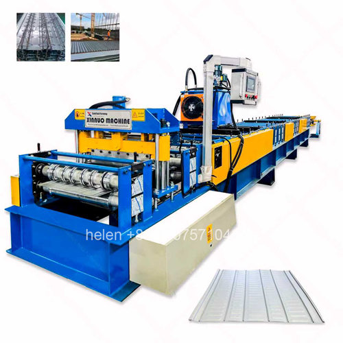
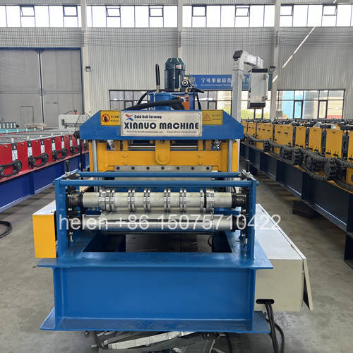
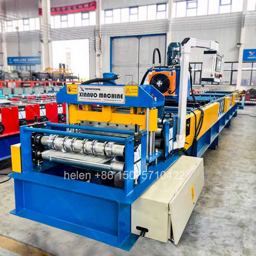
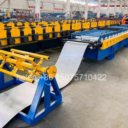
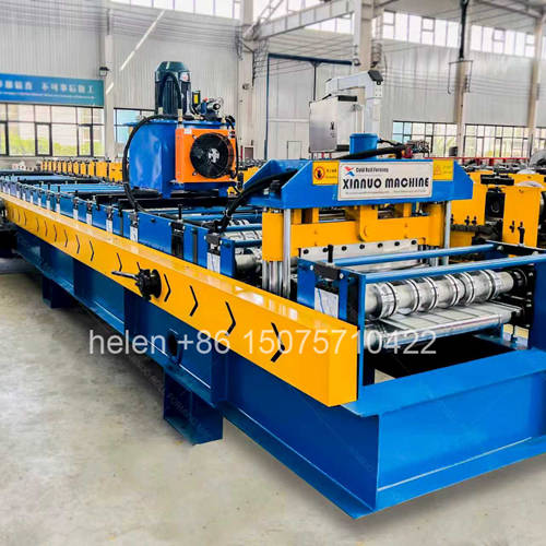
- The forming machine is one stage in a multi-stage production line
- Line output is set by the slowest stage, not by the fastest
- Truss welding and positioning usually cycle slower than forming
- Buying the former alone risks a line that cannot be balanced
- Buffering between stages absorbs differences in cycle time
- Panel handling is complicated by the protruding truss
- Nesting and transport provision should be designed, not improvised
A truss slab floor deck is not produced by a single machine. The base sheet is roll formed and cut, a rebar truss is fabricated and welded, the truss is positioned and welded to the sheet, and the finished panel is stacked and dispatched. Four distinct stages, each with its own cycle time, must fit together into one production flow. Output is determined by whichever stage is slowest, which is why the roll forming machine is not automatically the constraint in a truss slab line — and why a line assembled from separately chosen machines frequently underperforms even though every individual machine is capable.
This page addresses the balancing of a truss slab production line: what sets the cycle time at each stage, why the forming machine is rarely the true bottleneck, where the constraint actually moves as volume changes, how buffering between stages accommodates differences in cycle time, what balancing options exist and what each costs, how panel handling and nesting are complicated by the protruding truss, what should be measured to keep the line balanced once it is running, and what layout requirements follow from designing the stages to work together rather than in isolation.
| Stage | What Sets the Cycle Time | Typical Constraint Character | Where Time Is Lost |
|---|---|---|---|
| Base sheet forming | Forming speed and panel length, with a fixed increment for cutting each panel | Continuous process. Rate is predictable and varies little from panel to panel once running. | Coil changes and any interruption upstream. The forming machine itself rarely varies its output. |
| Truss production | Assembly of chord and web bars and welding at every node along the truss length | Discrete process with a large number of individual weld operations, each short but cumulative | Weld sequence, positioning between nodes, and rework where a weld fails inspection |
| Truss to sheet assembly | Positioning the truss accurately and completing the welds that fix it to the base sheet | Most labour-intensive stage relative to its duration, because positioning accuracy has to be achieved before welding can start | Positioning and clamping, distortion correction, and inspection of the completed panel |
| Stacking and dispatch | Handling the finished panel, nesting it in the stack, and removing the stack | Depends on equipment and labour rather than on process | Manual handling of long panels with a protruding truss, and stack removal blocking the line |
| Reason | Explanation |
|---|---|
| Forming is continuous | A roll forming machine produces continuously once running. Welding is a series of discrete operations, each of which can vary, and variation accumulates where continuous processes do not. |
| Base sheet is thin and narrow | Truss slab base sheets are commonly around 590 mm wide and 0.5 to 1.2 mm thick, so the forming load is modest and the line runs at a comfortable rate. |
| Welding is inherently slower per unit of length | Producing a metre of roll formed sheet takes a fraction of the time required to weld the corresponding length of truss and its attachment to the sheet. |
| Positioning cannot be automated away entirely | Whatever the level of equipment, the truss must be located relative to the sheet within tolerance before welding, and that step takes time that forming does not. |
| Panel length is fixed by the project | Longer panels increase forming time proportionally but increase welding time more than proportionally, since weld count scales with truss length and node count. |
| The practical conclusion | Sizing the forming machine for a rate it will rarely be permitted to achieve wastes capability. It should be sized to serve the line, and the line should be designed around the assembly stage. |
| Scenario | Bottleneck Location | Symptom Observed | Appropriate Response |
|---|---|---|---|
| Short panels, high volume | Assembly stage, because the fixed positioning time per panel cannot be amortised over a long length | The forming line stands idle between panels while assembly catches up | Increase assembly capacity or reduce per-panel positioning time rather than increasing forming speed |
| Long panels, low volume | Truss production, since weld count scales with length | Formed sheets accumulate waiting for trusses | Buffer base sheets and run truss production ahead, or add truss production capacity |
| Frequent truss height changes | The changeover itself, at truss production and assembly | Output drops on days with mixed orders despite the forming line running normally | Batch by truss height, accepting a longer overall run for fewer changes |
| Long coil runs but short order quantities | Coil change and setup, upstream of everything | The forming line is stopped more often than any downstream stage | Batch orders by base sheet specification and stage coil in advance |
| Stack removal blocking the line | Dispatch, effectively | The line stops with a completed panel still on the discharge because the stack is full | Lifting provision and a defined maximum stack height so the stack can be removed promptly |
| Inspection and rework | Inspection station | Completed panels waiting on weld inspection before they can be stacked | In-process inspection at each node rather than a final check, so rework is caught before the panel is finished |
| Buffer | Purpose | Practical Provision | Risk If Absent |
|---|---|---|---|
| Formed sheet buffer | Decouples the forming line from assembly so neither waits on the other | Defined floor area where formed sheets can be stacked temporarily without marking or distortion | The forming line stops every time assembly pauses, and assembly waits whenever forming runs slowly |
| Truss buffer | Allows truss production to run in campaigns independent of panel assembly | Racking for completed trusses at each height, protected from distortion and corrosion | Truss production becomes the pacing stage for every panel, and a truss equipment fault stops the whole line |
| Coil buffer | Keeps coil staged so changes do not require retrieval | Two or three coils of the required blank width staged at the decoiler | Every coil change begins with a retrieval task the machine cannot compensate for |
| Dispatch buffer | Allows completed stacks to be removed without interrupting production | Space, lifting provision and a defined maximum stack height | The line stops with a finished panel on the discharge because the stack cannot be moved |
| Buffer sizing principle | Cover the longest realistic interruption in the downstream stage | Set against the actual repair or changeover time, not an arbitrary quantity | An undersized buffer provides no decoupling; an oversized one ties up material and floor area unnecessarily |
| Option | Effect on the Line | Cost and Consideration |
|---|---|---|
| Increase forming speed | Raises upstream capacity, which is of no benefit if assembly is the constraint | Higher tier machine, higher cost, and no line-level gain unless the constraint is genuinely upstream |
| Add assembly capacity | Attacks the constraint directly where assembly is the pacing stage | Additional equipment and, more significantly, additional trained labour |
| Run truss production in campaigns | Removes truss production from the per-panel cycle time by feeding a buffer | Requires buffer storage and discipline in keeping it stocked at each truss height |
| Batch by truss height | Reduces changeover frequency, which is often the largest single source of lost line output | Requires order book visibility and the willingness to hold finished stock |
| Batch by base sheet specification | Reduces coil changes and setup on the forming line | Requires planning across the order book rather than order-by-order execution |
| Increase buffer quantities | Absorbs variation between stages without changing their capability | Floor area and working capital tied up in semi-finished material |
| Improve handling and dispatch | Removes the stops caused by full stacks and manual panel movement | Lifting provision and a defined nesting and stacking method — usually the cheapest significant gain available |
| Move inspection in-process | Prevents rework being discovered at the end of the panel | Requires inspection criteria per node and trained operators to apply them |
| Characteristic | Implication |
|---|---|
| Protruding truss | Panels cannot be stacked flat on one another in the way plain deck sheets can. The truss of one panel bears on the panel below, so nesting and support provision must be designed. |
| Panel length up to 12 m | Handling cannot be manual. Lifting provision and a defined handling method are requirements rather than conveniences. |
| Truss distortion risk in handling | The truss is a lightweight lattice. Improvised lifting, or lifting at a single point, can deform it, which affects the structural depth the design assumed. |
| Base sheet visible from below | The sheet surface is a finished quality requirement. Handling that marks the underside of the sheet produces a visible defect in the completed floor. |
| Stack height and stability | Nested stacks are taller per panel than plain sheets, so transport is governed by volume as much as by weight. |
| Transport restraint | Movement in transit distorts trusses and marks sheets. Restraint arrangements should be specified for the panel type rather than adapted from plain sheet practice. |
| Site lifting | The delivery pack is lifted as a unit onto the floor under construction, so pack configuration affects how efficiently the panels can be placed. |
| Identification | Panels of different truss heights look similar in a stack. Clear identification prevents a panel being installed in the wrong location. |
| Measure | What It Reveals | Action Trigger |
|---|---|---|
| Panels completed per shift | The line-level output, which is the only figure that matters commercially | Tracked against plan; a persistent shortfall points to the pacing stage |
| Time per stage per panel | Identifies which stage is actually pacing the line, rather than which one feels slowest | Where one stage consistently exceeds the others, the constraint has been located |
| Forming line utilisation | How much of the forming machine's capability is actually being used | Low utilisation with high upstream capability confirms the constraint is downstream |
| Changeover count and duration | The recurring loss from switching truss heights and coil specifications | Where changeover exceeds a defined share of the shift, batching should be introduced |
| Rework and rejection rate | The cost of weld defects and distortion discovered after the panel is complete | Where rejection is significant, inspection should move in-process |
| Buffer levels | Whether the buffers are actually decoupling the stages or have become stores | A buffer that never falls suggests over-provision; one that is always empty provides no decoupling |
| Stops caused by full stacks | How much production time is lost to dispatch rather than to production | Any recurring stop here is a handling problem, not a machine problem |
| Requirement | Reason |
|---|---|
| Single direction of flow | Coil enters at one end, finished panels leave at the other. Reversing or crossing flows between the forming line and the assembly area creates handling conflicts. |
| Forming line length provision | The forming line, cut-off and run-out occupy a substantial length, and panels up to 12 m must be supported as they discharge. |
| Assembly area adjacent to the forming discharge | Formed sheets should move the shortest possible distance to the assembly position, and the movement should not require lifting. |
| Truss production positioned to feed assembly | Trusses should arrive at the assembly position without an intervening handling operation. |
| Buffer areas identified and bounded | Buffers that are not defined become uncontrolled accumulation, which obstructs movement and hides the real constraint. |
| Dispatch area with lifting provision | The stack must be removable as a unit, or the line will stop waiting for it to be cleared. |
| Headroom | Lifting equipment must pass over the line and over the stacked panels, including the truss height above the sheet. |
| Floor loading | Coil, semi-finished sheets and nested panel stacks all impose load. Positions should be assessed rather than assumed. |
| Walkways clear of all three flows | Coil in, formed sheets through, finished panels out — pedestrians should not be in any of them. |
| Information | Why It Determines the Balance |
|---|---|
| Panel length range and distribution | Short and long panels move the constraint between stages. The distribution matters more than the maximum. |
| Truss height range and change frequency | Each height change costs setup time at truss production and assembly. |
| Base sheet drawing and specification | Sets the forming time and the coil change frequency on the forming line. |
| Required annual output | The figure against which line capacity must be designed, expressed in panels or in floor area. |
| Weld process, sequence and inspection regime | Determines the assembly stage cycle time, which is usually the pacing stage. |
| Assembly equipment and manning intended | Establishes what the assembly stage can achieve before the forming machine is sized. |
| Available floor area and headroom | Constrains buffer quantities, nesting provision and the layout that is possible. |
| Lifting provision available | Determines whether stacks can be removed promptly or whether dispatch will pace the line. |
| Transport arrangement for finished panels | Nesting and pack configuration follow from the transport method, and transport constraints feed back into panel length. |
| Order pattern and batch sizes | Determines how much benefit batching can deliver against changeover loss. |
| Parameter | Standard Range |
|---|---|
| Product produced | Truss floor slab panel comprising a roll formed galvanized base sheet with a welded rebar truss fixed to it |
| Line stages | Base sheet forming, truss production, truss to sheet assembly, cutting, stacking and dispatch |
| Base sheet thickness | 0.5 – 1.2 mm galvanized steel coil |
| Base sheet width | Commonly around 590 mm, produced to the buyer's drawing |
| Truss height | Commonly 80 mm, 120 mm, 180 mm and 280 mm |
| Chord bar diameter | Typically 6 – 12 mm |
| Web bar diameter | Typically 4 – 8 mm |
| Panel length | Commonly 1.0 – 12.0 m, subject to transport and site access |
| Forming rows | Set by the base sheet section detail; a 590 mm class truss profile has been produced on a 26 row configuration |
| Frame | 350H welded H-section on the reference 590 mm class configuration |
| Mid plate | 16 mm on the reference configuration |
| Shaft | Φ70 mm on the reference configuration, sized to the narrow base sheet roll face |
| Drive | 7.5 kW on the reference configuration, with variable frequency drive and overload protection |
| Transmission | 1 inch roller chain on the reference configuration |
| Shear | Hydraulic post-cut shear, with blade condition and clearance maintained for clean edges on galvanized material |
| Cut length tolerance | ±1.5 mm, held across the full panel length range |
| Truss production | Chords and web bars assembled and welded to the specified height, with web spacing and angle control |
| Assembly | Truss positioned to the drawing and welded to the base sheet, with distortion control on the thin sheet |
| Buffer provision | Formed sheet buffer, truss buffer by height, staged coil, and a dispatch area sized for prompt stack removal |
| Handling | Nesting and lifting provision suited to panels with a protruding truss, with support arranged to prevent truss distortion |
| Layout | Single direction of flow from coil to dispatch, with forming discharge adjacent to the assembly position and headroom for lifting throughout |
| Control system | PLC with colour touchscreen HMI, programmable cut length, sheet count control and stored recipe banks |
| Electrical supply | 380 V / 50 Hz / 3-phase standard; alternative voltages and frequencies by destination |
| Certification | CE marking and ISO 9001:2015 compliant manufacturing, with destination-market documentation arranged as required |
Coil loading on the decoiler, strip entry through the guide, progressive forming of the base sheet section, length measurement, hydraulic cutting, discharge to the assembly position, positioning and welding of the rebar truss to that sheet, and nesting of the completed panel for dispatch follow the established sequence, with the forming stage sized to serve the line rather than to set its pace.
Hebei Xinnuo is a professional cold roll forming machinery manufacturer with 20+ years of experience. We specialize in C/Z purlin machines, roof panel roll formers, floor deck machines, and custom profile solutions — exported to 50+ countries worldwide.