helen@hbxinnuorollforming.com
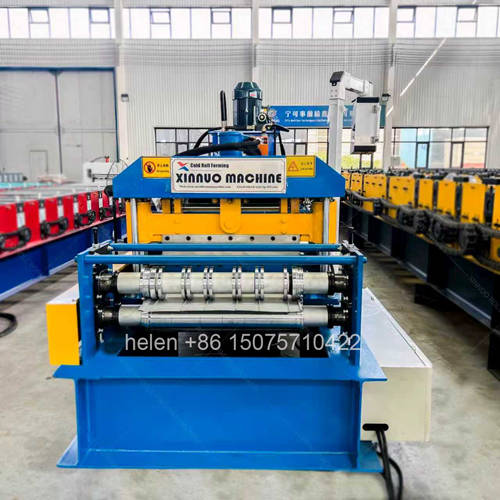
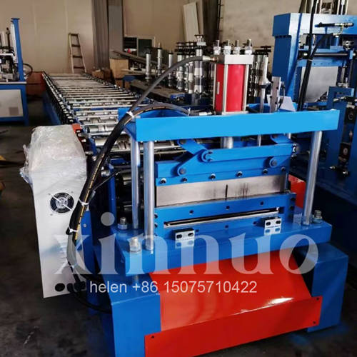
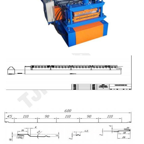
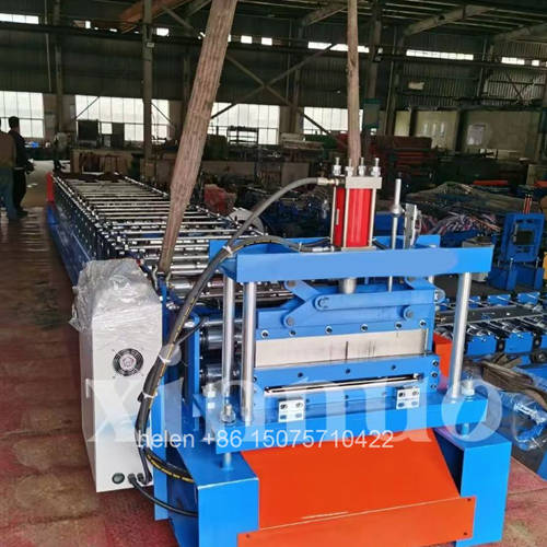
- A truss floor slab welds a rebar truss onto a profiled steel base sheet
- The truss replaces reinforcement that would otherwise be placed on site
- Base sheet runs 0.5 to 1.2 mm galvanized at around 590 mm width
- Truss heights span roughly 80 to 280 mm across four common levels
- Main bars run 6 to 12 mm and web bars 4 to 8 mm in diameter
- Production combines base sheet forming with truss welding in one line
- Truss height and span range determine the machine configuration
A truss floor slab is a composite formwork system assembled in a factory rather than on site. A profiled galvanized steel base sheet is formed by roll forming, and a welded rebar truss is fixed to it — top chord, bottom chord and diagonal web bars welded into a triangular lattice and then joined to the base sheet. The result is a panel that carries the wet concrete and construction loading during the construction stage, can act as lateral bracing to the steel frame, and then works together with the hardened concrete in the service stage to carry the floor loads.
This changes what a production machine has to do. A conventional deck machine forms a profile and cuts it to length. A truss floor slab forming machine produces the base sheet and then has to position and weld a reinforcement truss onto it with sufficient accuracy and consistency that the panel performs as a structural element. This page sets out what a truss floor slab consists of, how it differs from plain composite deck, the two production stages involved, how the base sheet specification drives the forming machine, what the truss geometry range means for configuration, the welding and quality requirements that apply, the standards referenced in the market, and where the system is used.
| Component | Function | Typical Specification |
|---|---|---|
| Base sheet | Permanent formwork for the wet concrete, and the surface that remains visible from below in the finished floor | Galvanized profiled steel sheet approximately 0.5 – 1.2 mm thick, around 590 mm wide, roll formed from coil |
| Top chord bar | Compression element of the truss in the construction stage, and part of the reinforcement in the service stage | Rebar typically 6 – 12 mm in diameter, running the full length of the panel |
| Bottom chord bars | Tension element of the truss, seated in or adjacent to the base sheet | Two bars, typically of similar diameter to the top chord |
| Web bars | Diagonal members forming the triangular lattice that connects the chords and provides shear transfer | Typically 4 – 8 mm in diameter, arranged in a continuous zigzag along the truss |
| Truss height | Distance between the chord levels, which determines the effective structural depth of the panel | Commonly 80 mm, 120 mm, 180 mm and 280 mm, corresponding to span ranges of roughly 3 – 6 m |
| Support bars | End reinforcement provided at supports, where the panel bears on the steel beams | Added at the ends of each panel, either in the factory or on site depending on the system |
| Panel length | Dictated by the span between supporting beams | Commonly produced between 1.0 m and 12.0 m, subject to transport and site access |
| Welds | Transfer load between the truss and the base sheet, and hold the truss geometry during handling and concreting | Welded connections between the truss members and between the truss and the base sheet |
| Aspect | Plain Composite Deck | Truss Floor Slab |
|---|---|---|
| Reinforcement | Placed on site, over the deck, as a separate operation | Factory-welded into the panel, removing the site fixing operation for the main bars |
| Base sheet | A structural deck profile with deep ribs and embossments to grip the concrete | A thinner, shallower profiled sheet acting primarily as permanent formwork, since the structural depth is provided by the truss |
| Sheet thickness | Typically 0.8 – 1.5 mm | Typically 0.5 – 1.2 mm, since the truss rather than the sheet provides the stiffness |
| Panel width | Determined by the deck profile, commonly 688 – 1025 mm | Commonly around 590 mm, set by the truss system and the base sheet module |
| Construction stage performance | The deck section provides the stiffness; temporary propping is often required depending on span | The truss provides the stiffness, which is what allows longer spans without the same degree of temporary support |
| Production equipment | Roll forming line with shear and discharge | Roll forming line plus truss production and welding equipment, combined into one production flow |
| Quality consideration | Section dimensions and embossment condition | Section dimensions plus weld quality, truss position accuracy and truss geometry |
| Stage | Equipment | Output | Key Control |
|---|---|---|---|
| Base sheet forming | Roll forming machine with decoiler, forming train, shear and discharge | Profiled galvanized base sheet cut to the required panel length | Section accuracy across the sheet width, cut length tolerance, and surface condition on galvanized material |
| Truss production | Truss welding equipment for assembling chord and web bars into the lattice | Welded rebar truss of the required height and length | Truss height accuracy, web bar spacing and angle consistency, and weld quality at every node |
| Truss to sheet assembly | Positioning and welding arrangement that fixes the truss onto the formed base sheet | Completed truss floor slab panel | Truss position relative to the sheet, weld integrity between truss and sheet, and freedom from distortion |
| Cutting and stacking | Cutting arrangement and stacking provision | Panels at the required length, stacked for transport | Cut squareness, length accuracy, and stacking that does not deform the truss or mark the sheet |
| Parameter | Typical Range | Machine Consequence |
|---|---|---|
| Sheet thickness | 0.5 – 1.2 mm galvanized | Thinner than a structural deck base sheet, so the forming train is lighter than a deck machine but must handle thin material without distortion or surface marking |
| Sheet width | Commonly around 590 mm | Narrower roll face and shaft length than a conventional deck machine, with the corresponding reduction in forming load per pass |
| Coil blank width | Established from the base sheet drawing | Determines the decoiler working width and the entry guide range |
| Profile depth | Shallow relative to structural deck, since the truss provides the structural depth | Fewer forming rows than a deep deck profile, but sufficient to develop the base sheet section without buckling the thin material |
| Surface | Galvanized, sometimes with a protective coating | Guides and wheels must protect the surface, since the base sheet remains visible from below in the finished floor |
| Panel length | Commonly 1.0 – 12.0 m | Run-out support, length measurement accuracy and stacking provision must suit the full length range |
| Length tolerance | Set by the project and by the acceptance requirements applied to the finished floor | Cut length control must hold accuracy across the full panel length rather than only on short panels |
| Parameter | Configuration |
|---|---|
| Profile class | 590 mm class truss profile |
| Forming rows | 26 rows |
| Frame | 350H welded H-section |
| Mid plate | 16 mm |
| Shaft | Φ70 mm |
| Drive | 7.5 kW |
| Chain | 1 inch |
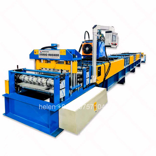
This is a documented production configuration from the manufacturers' archive for a 590 mm class truss profile. The row count is high relative to the sheet thickness because a finely detailed base sheet section requires more passes than its shallow overall depth would suggest — a light sheet with several small formed features needs a longer train to develop each feature progressively without distorting the material.
| Item | Requirement | Why It Matters |
|---|---|---|
| Weld integrity at truss nodes | Sound welds at every junction between chord and web bars | The truss carries the construction load. A defective node reduces the truss to a series of unconnected bars. |
| Truss to base sheet welds | Sufficient weld length and quality to fix the truss to the sheet and transfer load | These welds hold the truss in position during handling, placement and concreting, when the panel is most vulnerable to distortion. |
| Truss height accuracy | Consistent within the truss height band specified for the project | Truss height sets the effective structural depth of the composite section. Variation reduces the load capacity the design assumed. |
| Truss position on the sheet | Positioned to the drawing across the sheet width and along its length | Mispositioned trusses reduce cover and can affect the concrete cover to the top chord in the finished slab. |
| Web bar geometry | Consistent spacing and angle of the diagonal members | The lattice pattern is what provides composite behaviour. Irregular spacing concentrates stress at individual nodes. |
| Distortion control | Welding sequence controlled to limit distortion of both the truss and the thin base sheet | Heat input on a thin galvanized sheet distorts it readily, and a distorted base sheet affects the flatness of the finished floor. |
| Coating protection at welds | Welded areas treated to maintain corrosion protection where the specification requires it | Welding removes the galvanized coating locally, and those points become the first sites of corrosion in the finished floor. |
| Panel flatness | Consistent with the acceptance requirement applied to the finished floor | Flatness requirements are applied to the constructed floor, and a base sheet that is not flat makes them harder to achieve. |
| Standard | Scope and Relevance |
|---|---|
| Composite floor slab design and construction code | Covers the design and construction of composite floor slabs, which is the structural basis on which truss floor slab systems are specified. Design assumptions such as truss height and bar arrangement originate here. |
| Concrete structure construction quality acceptance code | Sets acceptance requirements for the constructed floor, including flatness criteria expressed as a permissible deviation over a two metre length. These criteria flow back into the panel flatness the machine and assembly process must deliver. |
| Reinforcement welding requirements | Govern weld quality at the truss nodes and in the truss to sheet connection, and determine the welding procedure and inspection regime applied in production. |
| Design codes for the destination market | Where the panels are exported, the structural design basis is that of the destination market. Truss geometry, bar diameters and truss heights are frequently specified to a local system rather than a generic one, so the drawing governs. |
| Practical point | The buyer's own base sheet drawing and truss arrangement drawing are the authoritative inputs. The applicable standards establish the requirements the panel has to satisfy, but the drawing is what the machine tooling is produced to. |
| Application | Why the Truss System Fits |
|---|---|
| High-rise steel frame floors | The truss provides stiffness during construction, reducing reliance on temporary propping and shortening the floor cycle. |
| Long span floor plates | Truss heights of 180 mm and 280 mm correspond to longer spans, which a shallow plain deck profile cannot reach without heavier sheet or closer supports. |
| Projects where site reinforcement is constrained | Factory welding of the main bars removes a site operation, which matters where labour availability or site access limits the construction programme. |
| Floors where the soffit remains exposed | The base sheet forms the visible underside of the finished floor, so the sheet surface condition is a finished quality requirement rather than a temporary one. |
| Floors requiring lateral bracing during construction | The installed panel can act as lateral restraint to the steel frame before the concrete is placed, contributing to frame stability during erection. |
| Prefabricated construction programmes | Factory assembly of the reinforcement into the panel suits programmes built around off-site manufacture and rapid installation. |
| Information | Why It Determines the Specification |
|---|---|
| Base sheet drawing | The authoritative input for tooling. Section form, rib detail, cover width and blank width all read from the drawing. |
| Truss arrangement drawing | Defines truss height, chord bar diameters, web bar diameter and pitch, and the weld arrangement between truss and sheet. |
| Truss height range to be produced | Determines the truss production equipment and the changeover provision between heights. |
| Base sheet thickness range | Sets the forming train configuration and governs surface protection requirements on thin galvanized material. |
| Panel length range | Drives run-out support, length measurement accuracy, cutting provision and stacking arrangements. |
| Required production rate | Determines whether base sheet forming and truss assembly are balanced, and whether the line needs buffering between stages. |
| Welding process and inspection requirement | Establishes the welding equipment, the inspection regime and the documentation expected by the destination market. |
| Coating and corrosion requirement | Affects base sheet specification and the treatment of welded areas. |
| Destination market and documentation | Standards, drawing conventions and documentation language differ by market and must be confirmed before manufacture. |
| Workshop layout and available space | A combined forming and truss assembly line is longer than a plain forming line, and the two stages must be laid out so material flows in one direction. |
| Parameter | Standard Range |
|---|---|
| Product produced | Truss floor slab panel comprising a roll formed galvanized base sheet with a welded rebar truss fixed to it |
| Base sheet thickness | 0.5 – 1.2 mm galvanized steel coil |
| Base sheet width | Commonly around 590 mm, produced to the buyer's drawing |
| Truss height | Commonly 80 mm, 120 mm, 180 mm and 280 mm, corresponding to span ranges of roughly 3 – 6 m |
| Chord bar diameter | Typically 6 – 12 mm |
| Web bar diameter | Typically 4 – 8 mm |
| Panel length | Commonly 1.0 – 12.0 m, subject to transport and site access |
| Forming rows | Set by the base sheet section detail; a 590 mm class truss profile has been produced on a 26 row configuration |
| Frame | 350H welded H-section on the reference 590 mm class configuration; selected against the base sheet section and thickness |
| Mid plate | 16 mm on the reference configuration |
| Shaft | Φ70 mm on the reference configuration, sized to the narrow base sheet roll face |
| Forming wheels | 45# forged steel, quenched to HRC 45 – 50, finish turned, keyed, polished and chrome plated |
| Drive | 7.5 kW on the reference configuration; variable frequency drive with overload protection |
| Transmission | 1 inch roller chain on the reference configuration |
| Shear | Hydraulic post-cut shear, with blade condition and clearance maintained for clean edges on galvanized material |
| Cut length tolerance | ±1.5 mm, held across the full panel length range |
| Truss production | Chords and web bars assembled and welded into the lattice at the specified height, with web spacing and angle control |
| Truss to sheet welding | Truss positioned to the drawing and welded to the base sheet, with distortion control on the thin sheet |
| Surface protection | Guides and forming wheels specified to protect the galvanized surface, since the base sheet remains visible in the finished floor |
| Coating at welds | Welded areas treated where the corrosion specification requires it, since welding removes the coating locally |
| Control system | PLC with colour touchscreen HMI, programmable cut length, sheet count control and stored recipe banks |
| Electrical supply | 380 V / 50 Hz / 3-phase standard; alternative voltages and frequencies by destination |
| Certification | CE marking and ISO 9001:2015 compliant manufacturing, with destination-market documentation arranged as required |
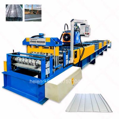
Coil loading on the decoiler, strip entry through the guide, progressive forming of the base sheet section across the roll train, length measurement, hydraulic cutting, discharge of the formed sheet to the assembly position, positioning and welding of the rebar truss to that sheet, and stacking of the completed panel follow the established sequence, with the base sheet geometry set by the roller tooling and the truss geometry set by the truss production equipment.
Hebei Xinnuo is a professional cold roll forming machinery manufacturer with 20+ years of experience. We specialize in C/Z purlin machines, roof panel roll formers, floor deck machines, and custom profile solutions — exported to 50+ countries worldwide.