helen@hbxinnuorollforming.com
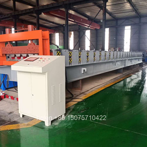
- Deck machines are custom built and difficult to modify after shipping
- Factory inspection verifies the forming train, not the paintwork
- A test run should produce panels at the specified gauge and profile
- Measured dimensions matter more than photographs of the machine
- Forming row count and drive configuration are the core checks
- Documentation handover is part of acceptance, not an afterthought
- Acceptance criteria should be agreed before the order is placed
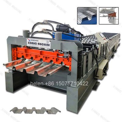
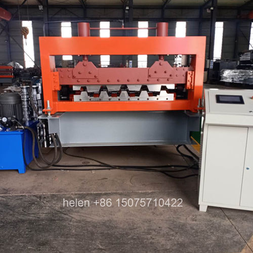
A floor deck forming machine is a custom-built heavy machine, and by the time it is installed on the buyer's floor it is thousands of kilometres from where it was made. Corrections that would be routine in the factory become freight, time, and argument once the machine has shipped. This makes pre-shipment verification disproportionately valuable: a defined test run at the manufacturer's works, a measured panel rather than a photographed machine, and a documented handover are the cheapest insurance available on a purchase of this size.
This page sets out what should be verified on a floor deck forming machine before it leaves the factory, what a meaningful test run produces, how the test panel should be measured and against what tolerances, which aspects of the forming train cannot be assessed from photographs, what documentation should be handed over with the machine, how acceptance criteria should be framed so that they are enforceable rather than aspirational, and what remains to be checked after the machine arrives on site.
| Area | What to Inspect or Verify | Why It Matters |
|---|---|---|
| Forming row count | Count the rows on each deck and confirm against the agreed specification for the profile and thickness | The row count is the single most important determinant of whether deep-rib material will form without jamming. It cannot be increased after manufacture without rebuilding the machine. |
| Drive configuration | Confirm the motor count and rating, and the chain size and type actually fitted | Dual motors and a heavy chain are the difference between forming thick, deep material and stalling part-way through it. |
| Frame and mid plate | Measure the frame section and flange thickness, and confirm the mid plate dimension | Frame rigidity and mid plate thickness carry the forming load. A lighter frame than specified shows up as deflection and inconsistent formation rather than as an obvious failure. |
| Shaft diameter and finish | Measure shaft diameter at several positions and confirm the ground and plated finish | Shaft stiffness governs how consistently the profile is formed across its width, particularly at the highest-load rows. |
| Wheel material and hardness | Confirm the material grade, the hardness achieved, and the number of manufacturing steps applied | Wheel hardness determines service life and how long the profile stays within tolerance. It is also the easiest specification to quietly reduce. |
| Embossment row provision | Confirm the clutch arrangement at the dimple wheel row and verify its operation | The embossing wheel is the origin of most pooling. This is a functional feature that should be demonstrated, not assumed from a description. |
| Bearing-mounted rear wheels | Identify which rows are fitted with them and count how many | Determines whether the rear of the train pushes or scrubs the material, which directly affects surface quality on coated stock. |
| Reinforcement bars | Confirm the rows at which reinforcement is fitted | Reinforcement at the correct rows — embossing, main drive, rib forming, sizing — maintains the roll gap under peak load. |
| Gear drive positions | Confirm which rows carry gear drives | Gear drives add feed and pull force at the highest-resistance positions. Their placement indicates whether the design was reasoned against the profile. |
| Shear configuration | Confirm cylinder count, mounting position, and the blade arrangement supplied | Determines cut edge quality, trim waste, and whether panels discharge by gravity or require manual handling. |
| Entry guide and alignment | Check the guide range against the feed width and verify alignment to the first pass | Poor entry tracking concentrates load on one side of every pair of rolls and is a common source of uneven panels. |
| Control system and recipes | Verify the HMI, the recipe storage, sheet count control, and the fault display | Stored recipes remove manual parameter entry from changeovers and eliminate a recurring source of scrapped panels. |
| Guarding and safety provision | Confirm guards, interlocked access, emergency stops, and isolation provision | Safety provision is a conformity requirement and is far easier to verify before shipment than to rectify afterwards. |
| Machine dimensions and weight | Confirm overall length, width, height, and mass against the drawing supplied for site preparation | Discrepancies invalidate the foundation, access, and lifting arrangements already made for the machine. |
| Test Item | How It Should Be Performed | Acceptance Expectation |
|---|---|---|
| Test run on the specified profile | Using the actual profile ordered, not a similar profile that happens to be set up | Panels produced to the correct section, since a run on a different profile does not demonstrate that the ordered tooling performs correctly |
| Test run at the specified thickness | Using coil at the upper end of the thickness range ordered, not a convenient thinner coil | Clean forming with no jamming. Testing at nominal thickness conceals exactly the condition that causes pooling in service |
| Continuous run, not a short sample | Enough length to demonstrate that the train runs continuously without intervention | Several panels produced back to back. A single short sample does not show whether load builds up through the run |
| Shear operation across the full width | Cutting panels and examining both cut ends | Clean, consistent ends with no burring. Any edge condition should match what was specified for the blade option chosen |
| Both decks demonstrated | Running the second deck as well as the first, including a changeover between them | The changeover performed in the time expected and the second profile produced to specification |
| Cut length accuracy | Setting a length and measuring the panels produced across a run | Length accuracy held across multiple panels rather than only on the first |
| Sheet count control | Running a set count and confirming the machine stops at the correct number | Count accurate at the end of the run, since the count is the basis for invoicing and for confirming completion |
| Surface condition of the panels | Examining the full panel surface, on coated stock if that is what will be run | No scoring, burnishing, or marking. Surface defects are not visible in a photograph of the machine but are immediately visible on a panel |
| Emergency stop and safety functions | Operating the emergency stops and verifying that hazardous motion ceases and does not restart | All motion stops and restart requires a deliberate reset followed by a separate start command |
| Dimension | Method | Acceptance Expectation | What Deviation Indicates |
|---|---|---|---|
| Effective cover width | Measured across the finished panel at several points along its length | Consistent with the specified cover width within a defined tolerance | Roller spacing or material width variation; inconsistent measurements along the length indicate tracking problems |
| Rib height | Measured at several ribs and at several positions along the panel | Uniform across ribs and along the length | Uneven heights across the width indicate shaft deflection or an unbalanced forming load |
| Rib pitch | Measured between rib centres | Uniform and matching the drawing | Discrepancy indicates roller profile or spacing error, which affects how panels lap on site |
| Cut length | Measured on multiple panels from one run | Consistent with the set length across the run | Drift across the run points to encoder or length measurement issues rather than a setup problem |
| Squareness | Diagonal measurement across the panel end | Within tolerance | Out-of-square ends prevent panels lapping correctly and cause progressive alignment problems on site |
| Flatness along the panel | Panel placed on a flat surface or sighted along its length | No appreciable twist or waviness | Twist indicates insufficient forming rows or unbalanced drive through the train |
| Embossment condition | Visual and dimensional check of the dimples | Dimples formed consistently, with no coating damage | Inconsistent depth or coating damage indicates excessive embossing pressure or an unsupported dimple row |
| Surface finish | Full panel inspection, particularly on coated material | No scratching, burnishing, or pressure marks | Regularly spaced marks identify a specific wheel position; marks on one side indicate entry tracking |
| Aspect | Why a Photograph Is Not Evidence |
|---|---|
| Row count | A photograph of a machine frame does not show how many forming rows are present, and it is one of the specifications most easily reduced without any visible change to the machine's appearance. |
| Wheel material and hardness | Hardness is invisible. It requires either a test certificate or an on-site hardness check, and it determines how long the machine holds the profile. |
| Bearing provision in rear rows | Whether a wheel is keyed solidly to the shaft or mounted on bearings is hidden inside the assembly and cannot be assessed visually from outside the machine. |
| Clutch operation at the embossing row | A clutch that is fitted but does not release correctly produces the same pooling as one that is absent. It has to be demonstrated in operation. |
| Shaft diameter and straightness | Requires measurement. A shaft at the lower end of its stated tolerance behaves differently from one at the upper end under deep-rib forming load. |
| Chain size and type | Chain size is difficult to judge from a photograph but directly determines the feed force available through the train. |
| Surface quality produced | The condition of the panels is the outcome that matters, and the only reliable evidence is a panel produced on the machine and inspected. |
| Jamming behaviour under sustained load | Pooling appears after a period of running rather than immediately, so a photograph or a short video cannot demonstrate absence of the fault. |
| Document | Why It Should Be Handed Over With the Machine |
|---|---|
| Machine manual | Operating, setup, and maintenance information for the specific machine supplied, not a generic manual covering a range |
| Electrical schematic | Necessary for any fault finding. Without it, diagnosis of an electrical fault depends on tracing wiring on the machine |
| Hydraulic schematic | Essential for understanding the shear and any other hydraulic circuit, and for isolating a fault to a component |
| Profile drawing | Defines what the machine was built to produce and provides the reference for checking panels in the future |
| Parts list with references | Bearing, chain, seal, and component references allow parts to be ordered by model number rather than by description, which is the difference between an hour and two days |
| Blade specification | Allows replacement or regrinding to the correct hardness and geometry rather than to an approximation |
| Test run record | Documents the material used, the settings, and the panels produced, establishing a baseline against which later performance can be compared |
| Declaration of conformity | Supplied with the machine rather than on request, and required before the machine can lawfully be placed into service in many markets |
| Installation and foundation drawing | Confirms the dimensions, loadings, and utility requirements the site preparation was based on |
| Operation and training material | Video or written material lets new operators be trained without waiting on a revisit, which matters in operations with staff turnover |
| Criterion | Verification Method | Why It Should Be Written Before the Order |
|---|---|---|
| Profile dimensions | Measurement of a test panel against the agreed drawing | A tolerance agreed in advance is enforceable; a general requirement to meet the drawing is open to interpretation when a measurement is marginal |
| Cut length accuracy | Measurement across multiple panels from one run | Establishes whether accuracy is to be demonstrated on the first panel or maintained across a run |
| Surface condition | Panel inspection on the material type that will actually be run | Prevents the test being performed on uncoated material when production will run pre-painted coil |
| Continuous running | A run of a defined length or panel count without intervention | Demonstrates absence of pooling, which only becomes apparent over a sustained run |
| Both decks operational | Demonstration of each profile and a changeover between them | Confirms that the second product is genuinely available rather than notionally included |
| Safety functions | Operation of emergency stops and isolation provision | Safety acceptance is a requirement in most markets and should be demonstrated rather than certified on paper alone |
| Documentation complete | Checklist confirmed complete at handover | Documentation requested after delivery is routinely delayed or never supplied, so it should be a condition of acceptance |
| Spare parts supplied | Check against the agreed parts list | Parts agreed but not supplied are effectively lost, and the omission is usually discovered at the first breakdown |
| Check | Requirement |
|---|---|
| Condition on arrival | Inspect before unloading where possible. Transit damage and missing items are far easier to resolve before the machine is in position |
| Leveling verified | Confirmed longitudinally, transversely, and by diagonal check, with anchoring only after level is established |
| Alignment of the full line | Decoiler, entry guide, forming unit, shear, and output bracket aligned to one line, since misalignment between sections causes tracking problems that present as forming faults |
| Electrical connection verified | Supply voltage, phase, earthing, and isolation confirmed before first start |
| First production panel measured | Checked against the same criteria used at the factory test, on the coil that will actually be used in production |
| Level rechecked after first run | Anchoring and initial loading can both disturb the setting established before the run |
| Operators trained on the actual machine | The people who will run the machine present for commissioning, rather than represented by others who will not be operating it |
| Test run record retained | Site measurements added to the factory record so that a future performance question can be compared against the machine's own baseline |
| Parameter | Standard Range |
|---|---|
| Profile type | Open trapezoidal deck and closed re-entrant deck, produced to the buyer's profile drawing or a matched standard section |
| Effective coverage width | 688 – 1025 mm across the standard families; wider by drawing specification |
| Rib height | 39 – 153 mm depending on profile class |
| Forming rows | 18 – 36 rows, verified by count against the agreed specification |
| Frame | 400H – 450H welded H-section with 10 mm flange thickness and a 18 – 25 mm mid plate |
| Shaft | Φ90 – 115 mm round bar, rough turned then precision ground |
| Forming wheels | 45# forged steel, quenched to HRC 45 – 50, finish turned, keyed, polished, and chrome plated |
| Transmission | 2 inch external roller chain standard, 2.5 inch for the heaviest profiles |
| Motor configuration | 2 × 11 kW standard, 2 × 15 kW heavy, 2 × 22 kW above 1.5 mm material |
| Shear | Dual-cylinder hydraulic shear at floor level, with blade arrangement confirmed at inspection |
| Blade options | Three-blade for the cleanest edge with approximately 10 mm trim waste, or two-blade for zero waste with negligible edge deformation |
| Material capability | 0.8 – 1.5 mm standard; galvanized, aluminium-zinc coated, and pre-painted coil |
| Forming speed | 8 – 18 m/min depending on profile depth and material thickness |
| Cut length tolerance | ±1.5 mm, verified across multiple panels from a single run |
| Control system | PLC with colour touchscreen HMI, sheet count control, stored recipe banks, and plain-language fault display |
| Line length | Approximately 22 m overall, comprising a forming unit of about 14.5 m, a control section of about 3 m, and an output bracket of about 3 m |
| Forming unit width | Approximately 2,750 mm, with approximately 6,500 mm at the decoiler side |
| Documentation supplied | Machine manual, electrical schematic, hydraulic schematic, profile drawing, parts list, blade specification, and test run record |
| Electrical supply | 380 V / 50 Hz / 3-phase standard; alternative voltages and frequencies by destination |
| Certification | CE marking with Declaration of Conformity; ISO 9001:2015 compliant manufacturing |
Coil loading on the decoiler, strip entry through the guide, progressive forming across the roll train with embossment at the dimple row, sizing over the final passes, length measurement, dual-cylinder cutting at floor level, and gravity discharge to the stacking position follow the established sequence, and the test run at the works exercises that full sequence on the profile and gauge actually ordered.
Hebei Xinnuo is a professional cold roll forming machinery manufacturer with 20+ years of experience. We specialize in C/Z purlin machines, roof panel roll formers, floor deck machines, and custom profile solutions — exported to 50+ countries worldwide.