helen@hbxinnuorollforming.com
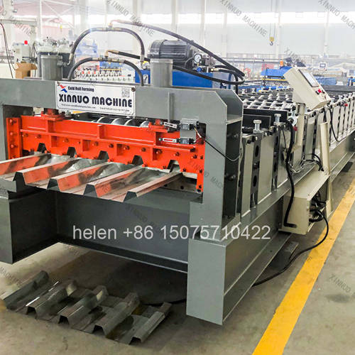
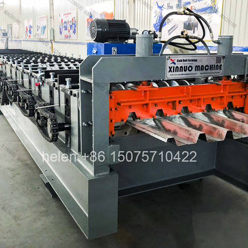
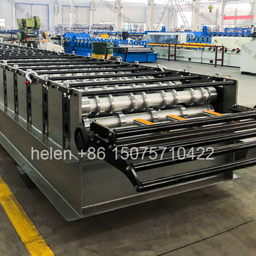
- Working, overall and blank width are three different figures
- Only working width is the sellable cover the customer buys
- Blank width minus overall width is edge trim, not formed geometry
- The ratio between them determines material yield per tonne
- A 57 mm rib class spans more than one working width variant
- Variants that share rib height still need different roller sets
- Yield differences between sections are a direct cost per panel
Metal deck is bought by the square metre of covered floor and produced from coil purchased by the tonne. Between those two units sits a ratio that determines the material cost of every panel: how much of the coil width ends up as sellable cover, and how much is consumed by ribs, side laps, and edge trim. For a 57 mm rib class section the ratio is different from a shallower deck and different again from a deeper one, and the section variants within the same rib height do not yield identically.
This page sets out the three width figures that are routinely confused in deck specification, uses the 57 mm rib height class as the worked example, explains why blank-to-cover ratio differs between sections and what that means commercially, sets out the variants available within the 57 mm class and what changes on the machine between them, addresses whether a single machine can serve more than one variant, and provides the selection logic for matching the machine to the section actually being specified. The designation is used across markets with different prefixes, so the governing reference is always the buyer's own section drawing rather than the label applied to it.
| Width | What It Measures | Why It Matters Commercially |
|---|---|---|
| Working width | The effective width of floor covered by one panel when lapped with the next | This is the product the customer buys and the basis on which the floor area is priced. It is set by the roller profile and is the figure quoted in the section designation. |
| Overall width | The physical width of the finished panel, wider than the working width by the amount absorbed in the side lap | Needed for transport planning, stacking, and site handling. It is not the same as the covered area, and confusing the two leads to under-ordering. |
| Blank width | The width of the flat coil that enters the machine | Determines what coil to buy, what the decoiler must accommodate, and the entry guide range. It is the largest of the three figures. |
| Formed material | Blank width minus overall width | Material absorbed into the ribs. It is not waste — it is the geometry that gives the panel its stiffness — but it does not cover floor, so it directly affects yield. |
| Edge trim | Material removed at the panel edges where the section requires a trimmed edge | Genuine waste. Reduced by a two-blade shear arrangement to zero, which is why shear choice affects material cost as well as edge quality. |
| Attribute | Typical Characteristic | Consequence for the Machine |
|---|---|---|
| Rib height | 57 mm | Mid-range deck depth: deeper than a shallow deck, shallower than a heavy structural section. Requires a forming train long enough to develop the rib progressively. |
| Working width variant, narrow | 750 mm working width, with an overall panel width around 801 mm | Roll and shaft length set to the section drawing; the finished cover is set by the tooling and not adjustable. |
| Working width variant, wide | 900 mm working width | A wider roller set and a wider blank requirement. The wider variant covers more floor per panel and fewer laps per square metre. |
| Designation prefix | Prefixes indicate whether the section is classified as load-bearing or as a wall or combined profile | The prefix describes the structural classification, not the forming difficulty. Two sections with the same rib height and prefix-difference can require very different roll tooling. |
| Material thickness | Commonly 0.5 – 0.8 mm for this rib class, with heavier gauges where a project specifies them | Sits comfortably inside the standard configuration envelope, and below the heavy tier, so the economy and standard configurations are usually sufficient. |
| Governing reference | The buyer's section drawing or national specification, not the shorthand label | Roll tooling is produced to the drawing. A machine built to an assumed geometry will not reproduce the specified section, regardless of designation match. |
| Factor | Effect on Material Consumed | Practical Implication |
|---|---|---|
| Rib depth | Deeper ribs consume more material per unit of cover, since the material must travel up and down each rib face | A deep section at the same working width needs a wider blank than a shallow one. This is inherent to the geometry and cannot be designed out. |
| Rib count at a fixed working width | More ribs at the same working width means more rib material and less flat cover within the panel | Two sections with identical working width can require different blank widths if their rib counts differ. |
| Rib face angle | Steeper rib faces consume more material per unit of height than shallower ones | Rib angle is a section design decision made by the engineer and reproduced by the tooling. It is not adjustable at the machine. |
| Side lap design | A deep interlocking lap consumes more material than a simple flat lap | Lap design affects the difference between overall and working width, which is why those two figures must both come from the drawing. |
| Edge trim requirement | A section requiring a trimmed edge consumes additional material that is then removed | Two-blade shearing removes this loss entirely, at the cost of a very slight corner deformation that does not affect structural performance. |
| Embossments | Dimples pressed into the rib faces draw material locally but do not change the blank width | Affects forming load and the anti-pooling requirement rather than material yield. |
| Consequence | Why It Matters to a Producer |
|---|---|
| Cost per square metre is not cost per tonne | Coil is bought by weight and panels are sold by covered area. A section that yields less cover per tonne carries a higher material cost per square metre even if the coil price is identical. |
| Wider working width reduces lap count | Fewer panels are needed to cover the same floor, which reduces the number of laps, the number of cuts, and the handling operations on site as well as the material consumed in laps. |
| Trim waste is a direct, avoidable cost | On a three-blade shear the per-cut trim is small per panel but cumulative across a project. It is one of the few material losses a producer can decide to eliminate. |
| Variant choice affects both yield and tooling cost | Moving from the narrow to the wide variant of the same rib height changes the material consumed per square metre and requires a different roller set — it is not a setting change. |
| Coil procurement follows the blank width | A blank width that is not commonly stocked locally raises coil cost and lead time, which can outweigh a yield advantage on paper. |
| Quotation accuracy depends on using the right width | Quoting from working width while buying from blank width understates material cost. The two figures must both be applied, and the difference is precisely where estimating errors occur. |
| Element | Effect of Moving to a Different Working Width in the Same Rib Class |
|---|---|
| Roller set | A different complete set of forming wheels. Roller profiles are specific to the section, so this is a tooling change rather than an adjustment. |
| Shaft and roll length | Longer rolls and shafts for the wider section, with the shafts suitable for the correspondingly wider forming face. |
| Blank width requirement | Changes with the section, since a wider working width requires a wider blank. The decoiler working width and entry guide range must accommodate the larger figure. |
| Forming load | A wider section presents more material to each pass at the same rib height, which increases the load and may move the configuration up a tier on the motor and chain specification. |
| Row count | Determined by rib height and thickness rather than by width, so two variants at the same rib height typically sit in the same row band. |
| Shear and blade arrangement | The shear must span the wider section, and the blade arrangement is profiled to the section geometry. |
| Coil handling | A wider blank generally means a heavier coil, which affects the decoiler load capacity and the lifting provision at the entry end. |
| Approach | When It Is Appropriate |
|---|---|
| Single section machine | Where one variant covers the market being served. The simplest, lowest cost, and most reliable option, and the right default unless there is a demonstrated second requirement. |
| Interchangeable tooling on one machine | Where the two variants share the same frame, drive, and shaft but use different roller sets. Changeover is a tooling operation taking appreciable time, not a shift of the entry guide. |
| Purpose-built switchable configuration | Where two closely related sections are both required regularly and the machine is engineered for the change, such as the paired-width switchable configurations used for deck production. Suitable when both sections genuinely run in production rather than occasionally. |
| Two machines | Where both variants run continuously and in volume. The capital cost is higher but the two products can be produced simultaneously and neither is lost to changeover. |
| The decision rule | Compare the changeover time and its cost against the annual volume of the smaller requirement. A second variant produced once or twice a year does not justify tooling or a switchable machine; one produced weekly usually does. |
| Information | Why It Must Be Established First |
|---|---|
| Section drawing or section property table | The authoritative input. Working width, overall width, blank width, rib geometry, and lap detail all read from it. |
| Working width and rib height | Identifies the variant and the row band. Rib height rather than working width drives the forming train length. |
| Blank width and coil specification | Determines what coil must be purchased, the decoiler working width, and the entry guide range. |
| Material thickness range | Sets the configuration tier. Establishing the maximum thickness rather than the typical one prevents a machine that pools at the upper end. |
| Coating type and finish | Determines the guide and wheel provision needed to protect the surface through forming. |
| Number of variants required | Decides between a single machine, interchangeable tooling, a switchable configuration, and two machines. |
| Annual volume per variant | The only sound basis for judging whether a second variant justifies tooling or a second machine. |
| Edge and shear preference | Determines whether trim waste is eliminated or accepted, which feeds directly into material yield. |
| Required panel lengths | Affects the run-out arrangement and the discharge bracket length. |
| Destination specification and documentation | Section dimensions, steel grade references, and documentation language differ by market and should be confirmed against the drawing rather than assumed from the designation. |
| Parameter | Standard Range |
|---|---|
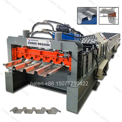
| Target section | 57 mm rib height deck class, produced to the buyer's section drawing; working widths including 750 mm and 900 mm variants |
| Working width | 750 mm and 900 mm variants within this rib class; the finished cover is set by the roller tooling |
| Overall panel width | Approximately 801 mm for the 750 mm working width variant, taken from the section drawing; the excess over working width is the side lap |
| Blank width | Established from the section drawing and confirmed before coil procurement; the decoiler and entry guide are sized to this figure |
| Rib height | 57 mm |
| Material thickness | Commonly 0.5 – 0.8 mm for this class; machine capacity extends to 1.5 mm and beyond on heavier sections |
| Material | Galvanized and coated steel sheet to the buyer's specification |
| Forming rows | Deck profile range of 18 – 36 rows; rib height and thickness determine the figure within that range |
| Frame | 400H – 450H welded H-section with 10 mm flange thickness and a 18 – 25 mm mid plate |
| Shaft | Φ90 – 115 mm round bar, rough turned then precision ground |
| Forming wheels | 45# forged steel, quenched to HRC 45 – 50, finish turned, keyed, polished, and chrome plated |
| Transmission | 2 inch external roller chain standard, 2.5 inch for heavy configurations |
| Motor configuration | 2 × 11 kW standard, 2 × 15 kW heavy, 2 × 22 kW above 1.5 mm material |
| Shear | Dual-cylinder hydraulic shear at floor level for balanced force and gravity-assisted panel discharge |
| Blade options | Three-blade for the cleanest edge with approximately 10 mm trim waste, or two-blade for zero trim waste with negligible edge deformation |
| Forming speed | 8 – 18 m/min depending on profile depth and material thickness |
| Cut length tolerance | ±1.5 mm |
| Control system | PLC with colour touchscreen HMI, sheet count control, and stored recipe banks |
| Line length | Approximately 22 m overall, comprising a forming unit of about 14.5 m, a control section of about 3 m, and an output bracket of about 3 m |
| Forming unit width | Approximately 2,750 mm, with approximately 6,500 mm at the decoiler side |
| Electrical supply | 380 V / 50 Hz / 3-phase standard; alternative voltages and frequencies by destination |
| Certification | CE marking and ISO 9001:2015 compliant manufacturing, with destination-market conformity documentation arranged as required |
Coil loading on the decoiler, strip entry through the guide, progressive forming across the roll train with embossment at the dimple row, sizing over the final passes, length measurement, dual-cylinder cutting at floor level, and gravity discharge to the stacking position follow the established sequence, with the section geometry set by roller tooling produced to the buyer's drawing and the blank width established from that drawing before coil is ordered.
Hebei Xinnuo is a professional cold roll forming machinery manufacturer with 20+ years of experience. We specialize in C/Z purlin machines, roof panel roll formers, floor deck machines, and custom profile solutions — exported to 50+ countries worldwide.