helen@hbxinnuorollforming.com
- Not every floor deck receives concrete, and the difference is fundamental
- A dry deck panel must carry the floor load entirely on its own
- Rib depth and gauge do more work without concrete to contribute
- Interlocking edges distribute load between adjacent panels
- Point load resistance matters as much as distributed load capacity
- Panels are walkable immediately, which sets stiffness requirements
- The machine is configured around stiffness, not around formwork duty
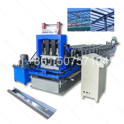
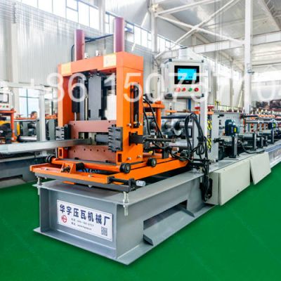
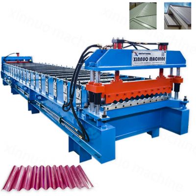
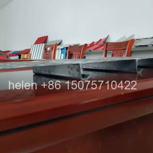
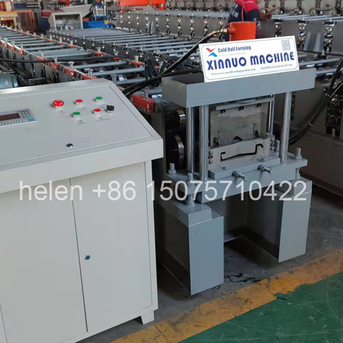
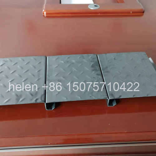
Most floor deck discussion assumes concrete. The deck is described as permanent formwork, the concrete is cast on top, and the deck either bonds with it to form a composite section or simply supports it until it cures. A non-concrete-casting floor decking machine produces something different: profiled steel panels used as the finished, dry, load-bearing floor of a mezzanine, an attic conversion, a modular building or a plant platform, with no concrete ever placed on top.
That single difference changes everything about how the panel has to perform and therefore about how the machine has to be specified. With no concrete to contribute stiffness and no slab to spread load, the panel provides all the strength and all the stiffness itself. It has to be safe to walk on the day it is installed, it has to resist concentrated foot traffic and point loads rather than a distributed slab load, its deflections have to be acceptable as a finished walking surface rather than as a temporary form, and its edges have to connect to neighbouring panels so that load is shared across a floor rather than concentrated on one sheet. This page sets out what the category covers, where the panels are used, what changes when there is no concrete, the profile and edge requirements that follow, how the machine is configured, and how it differs from a composite deck machine.
| Deck Type | Concrete Cast? | Structural Action | Character |
|---|---|---|---|
| Composite deck | Yes | Deck bonds with the concrete and acts as tensile reinforcement in the finished slab | Requires embossments and rib geometry designed for bond. The finished floor is a concrete slab and the deck is largely concealed. |
| Non-composite form deck | Yes | Deck acts only as permanent formwork and does not bond with the concrete | Reinforcement in the slab carries the design load, designed to the reinforced concrete code rather than on composite action. Depths are typically shallow, in the region of 15 mm and 25 mm. |
| Non-casting dry deck | No | The steel panel itself is the finished floor structure | This is the category a non-concrete-casting machine serves. The panel must carry the floor load permanently and be safe to walk on immediately after installation. |
| Why the distinction matters | — | — | Form deck and composite deck are both designed around concrete. A dry deck panel is designed around the absence of it, which is why its profile is deeper, its gauge is heavier, and its edges interlock. |
| Application | Requirement It Imposes on the Panel | Panel Character |
|---|---|---|
| Industrial mezzanine floors | Storage and pedestrian loading over a clear span with immediate use on installation | Deeper ribs and a heavier gauge than a form deck, with edges that connect adjacent panels |
| Attic and loft conversions | Lightweight floor over existing structure, installed without wet trades | Panel weight matters as much as strength, since the supporting structure may be existing and already loaded |
| Modular and prefabricated buildings | Floor installed as part of a factory or site assembly process, dry and fast | Consistent panel dimensions and clean edges, because panels are installed to a programme rather than to tolerance on site |
| Container conversions | Floor that is installed and immediately serviceable in a confined envelope | Panels sized to the module so that cutting on site is minimised |
| Plant platforms and walkways | Access floor exposed to foot traffic, with the possibility of a slip requirement | Surface condition becomes a specified requirement rather than an incidental one |
| Temporary and event structures | Floor that can be installed and removed repeatedly | Edge details that permit repeated assembly, and panel durability sufficient for repeated handling |
| Plant rooms and service floors | Floor carrying equipment and access requirements, often with openings | Edge stiffness sufficient to remain sound where panels are trimmed around openings |
| Factor | With Concrete | Without Concrete | Machine Consequence |
|---|---|---|---|
| Load path | Concrete slab carries most of the load; the deck acts as formwork or as tensile reinforcement | The steel panel carries everything, in both directions across its width and along its length | Rib geometry has to deliver stiffness directly, so rib depth and rib count carry more design significance |
| Stiffness source | Slab depth provides stiffness; deck thickness is relatively minor | Rib depth, rib count and material thickness are the only sources of stiffness | Deeper section heights and heavier gauges, which pushes the machine toward the heavy configuration tiers |
| Deflection limits | Assessed as a slab, largely concealed by finishes | Assessed as a finished walking surface, where perceptible deflection is unacceptable | Section accuracy matters more, because deflection depends on the section actually produced rather than a nominal one |
| Load type | Predominantly distributed load from the slab and imposed floor load | Concentrated foot traffic, point loads from stored items, and impact from dropped objects | Local stiffness matters, which is a function of rib pitch and the stiffness of the flats between ribs |
| Immediate serviceability | The deck must be safe during construction, but the floor is used only after curing | The panel is the working floor as soon as it is laid | No tolerance for panel distortion or edge defects, since defects are immediately present in the working surface |
| Load sharing between panels | Concrete distributes load across the whole slab | Load is shared only through the panel edges | Interlocking or overlapping edges are essential, and the edge profile becomes a critical part of the tooling |
| Surface role | Deck surface is covered | Panel surface is the floor, or the substrate for a finish laid over it | Surface condition and flatness are quality requirements rather than incidental characteristics |
| Profile Feature | Why It Matters Without Concrete | Machine Implication |
|---|---|---|
| Rib depth | Provides the section stiffness that the concrete would otherwise supply | Deeper forming requires more rows, larger wheels and a heavier frame and drive |
| Rib count and pitch | Governs local stiffness between ribs, which is what a point load is carried by | Tooling produced to the drawing, with the pitch set by the roller profile and not adjustable |
| Interlocking edge | The only path by which load is shared between adjacent panels | A dedicated edge forming provision within the roll train, and edge geometry reproduced to close tolerance |
| Rib flank angle | Steeper flanks give greater stiffness for the same rib depth but consume more material | Steep flank forming requires a longer forming sequence to develop the corner radii without tearing |
| Flat width between ribs | Forms the walking surface and carries point loads locally | Roller profile must provide consistent flat areas, since variation shows as a visually uneven floor |
| Longitudinal stiffening | Reduces deflection along the panel in the span direction | Additional formed features, requiring passes beyond those needed for the basic rib pattern |
| Anti-slip provision | Where the panel is the exposed walking surface, slip resistance may be specified | Either a formed surface texture or a separate applied treatment, which affects the machine specification |
| Material thickness | Directly increases both strength and stiffness where no concrete contributes | Heavier gauges move the machine up the configuration tiers and require more forming force and a heavier chain |
| Parameter | Guidance |
|---|---|
| Forming rows | Determined by rib depth and material thickness. Deeper ribs and heavier gauges require more rows, and the row count must be sufficient to develop both the rib pattern and the edge interlock progressively. |
| Frame | Selected against the forming load, which is higher than for a thin form deck because the material is heavier and the ribs deeper. Heavier gauges call for the heavy tier rather than the standard tier. |
| Shaft | Sized so that deflection does not open the roll gap at the highest-load rows, since a section that is slightly under-formed loses stiffness disproportionately when there is no concrete to compensate. |
| Drive | Sufficient power to form the heaviest gauge in the range at production speed, and to maintain feed force through a train that includes edge forming passes. |
| Transmission | A heavier chain is appropriate where material thickness is at the upper end of the range, since the forming load is carried by the drive rather than shared with a stiffening slab. |
| Edge forming provision | An integral part of the tooling rather than an add-on. The interlocking edge is a functional requirement of the panel, not a finishing detail. |
| Shear | Hydraulic post-cut shear sized to the material thickness, with blade condition maintained, since the panel edge is a finished edge that engages with the adjacent panel. |
| Cut length control | Programmable length with sheet count control. Panels are produced to the bay or module dimension, so length accuracy directly affects how well the floor fits together. |
| Surface provision | Guides and forming wheels finished to avoid marking, since the panel surface is either the finished floor or the substrate for it. |
| Run-out and handling | Sized to the longest panel produced, with handling provision that does not distort the rib pattern, since a distorted panel is a defective finished floor rather than a defective temporary form. |
| Edge Type | Function | Machine Requirement |
|---|---|---|
| Simple overlap | Panels lap over one another and are fixed through the lap | An edge formed to a consistent width so that the lap closes fully along the panel length |
| Interlocking profile | Formed edges engage with each other, locating panels and transferring some load across the joint | A matching pair of edge profiles, which must be formed to close tolerance to engage along the full panel length |
| Mechanical seam or clip | Adjacent panels are joined by a formed seam or a separate clip | Edge geometry designed to accept the seam or clip, with the fixing method agreed before tooling is produced |
| Support-bearing edge | The panel edge bears directly on the supporting beam or joist | An edge detail that seats properly and does not crush under the bearing load |
| The tolerance point | Edge engagement is cumulative along the floor | Edge profile tolerance must hold along the whole panel. A small error repeated across many panels accumulates into a floor that will not close up. |
| Item | Consideration |
|---|---|
| Panel to beam fixing | Self-drilling screws or similar through the panel into the supporting member. Fixing positions should suit the rib pattern so that fixings land in material, not in an open rib. |
| End bearing detail | The panel end must seat on the beam. Where the rib pattern reaches the end, an end detail may be required to provide a sound bearing surface. |
| Perimeter trimming | Floors rarely suit whole panels at the perimeter. Trimming detail should be considered at design stage, since trimming a deep rib can compromise the edge stiffness. |
| Openings and penetrations | Openings for services or access need edge reinforcement. Deep-rib panels cut for an opening lose local stiffness, and the reinforcement detail follows from the profile. |
| Access or lift-out panels | Where floor access is required, a panel or part-panel that can be removed and replaced needs an edge detail permitting repeated assembly. |
| Floor finish substrate | Where a board or screed-free finish is laid over the panels, the panel flatness becomes the substrate tolerance. Panels produced to a consistent flatness avoid levelling work later. |
| Edge trims and closures | Produced from the same coil as the panels, which makes them a natural addition to the order and to the machine specification. |
| Aspect | Composite Deck Machine | Non-Casting Dry Deck Machine |
|---|---|---|
| Design basis | The deck's contribution to a composite slab | The panel acting alone as the finished floor |
| Embossments | Essential, to bond with the concrete | Not required, since there is no concrete to bond with |
| Rib depth | Deep, to provide construction-stage stiffness before curing | Deep, but for a different reason — to provide permanent floor stiffness |
| Material thickness | Commonly 0.8 – 1.5 mm | Frequently heavier, because the panel carries the permanent load without a slab |
| Edge detail | Side lap for panel alignment, with concrete filling the joint | Interlocking or mechanically seamed edge that must transfer load between panels permanently |
| Surface requirement | Concealed by concrete; surface condition is of limited consequence | The panel surface is the floor or its substrate, so surface condition is a finished quality requirement |
| Deflection assessment | Assessed as a slab, with finishes masking small deflections | Assessed as a walking surface, where perceptible deflection is not acceptable |
| Anti-slip | Not applicable | Potentially specified where the panel is exposed to foot traffic |
| Information | Why It Determines the Specification |
|---|---|
| Panel section drawing | The authoritative input for tooling, including rib geometry, pitch, flat widths and the edge detail. |
| Edge interlock drawing | The interlocking detail is a matching pair of profiles and must be tooled as one system, not as two independent edges. |
| Span and support spacing | Determines the section depth and gauge the panel needs, which drives the machine tier. |
| Design load and deflection limit | Confirms whether the required section is within the machine's forming capability or requires a heavier configuration. |
| Material thickness range | Sets the drive, chain and frame requirement; the maximum matters more than the typical gauge. |
| Panel length and module dimension | Drives run-out provision, cut length control and handling arrangements. |
| Surface requirement | Determines whether anti-slip provision, a protective finish, or additional handling protection is needed. |
| Coating specification | Affects base material and the corrosion protection expected in the service environment. |
| Accessory requirement | Edge trims, closures and end details are usually produced from the same coil and should be specified with the main panels. |
| Destination market and documentation | Design standards, drawing conventions and documentation language differ by market and should be confirmed against the drawing before manufacture. |
| Parameter | Standard Range |
|---|---|
| Product produced | Dry load-bearing floor deck panel with an interlocking or seamed edge, produced to the buyer's section drawing |
| Design basis | The panel acting alone as the finished floor, designed for permanent distributed load, point load and deflection limits |
| Section depth | Deep rib form selected to provide stiffness without a concrete slab; the figure is established from the drawing and the span requirement |
| Rib pitch and flat widths | Set by the drawing; governs local stiffness under point load and the consistency of the walking surface |
| Edge detail | Overlapping, interlocking, or mechanically seamed to the buyer's drawing, formed as a matched pair of edge profiles |
| Material | Galvanized and coated steel coil; thickness typically heavier than a composite base sheet and established from the design load |
| Forming rows | Set by section depth, edge complexity and material thickness; sufficient to develop ribs and interlock progressively |
| Frame | Selected against forming load, normally the standard or heavy tier rather than an economy configuration |
| Shaft | Sized so that deflection does not open the roll gap at the highest-load rows |
| Forming wheels | 45# forged steel, quenched to HRC 45 – 50, finish turned, keyed, polished and chrome plated |
| Drive | Sufficient for the heaviest gauge in the range at production speed, with variable frequency drive and overload protection |
| Transmission | Heavier chain where material thickness sits at the upper end of the range |
| Shear | Hydraulic post-cut shear sized to the material thickness, producing a clean finished edge that engages the adjacent panel |
| Cut length tolerance | ±1.5 mm, held across the full panel length range, since length accuracy affects how the floor closes up |
| Forming speed | Set by section depth and material thickness; the appropriate rate is the one that holds section accuracy, not the highest available |
| Surface provision | Guides and wheels finished to avoid marking, since the panel is the finished floor or its substrate |
| Anti-slip provision | Formed surface texture or an applied treatment, specified where the panel is exposed to foot traffic |
| Run-out and handling | Run-out sized to the longest panel, with handling that does not distort the rib pattern |
| Accessories | Edge trims, closures and end details produced from the same coil as the main panels |
| Control system | PLC with colour touchscreen HMI, programmable cut length, sheet count control and stored recipe banks |
| Electrical supply | 380 V / 50 Hz / 3-phase standard; alternative voltages and frequencies by destination |
| Certification | CE marking and ISO 9001:2015 compliant manufacturing, with destination-market documentation arranged as required |
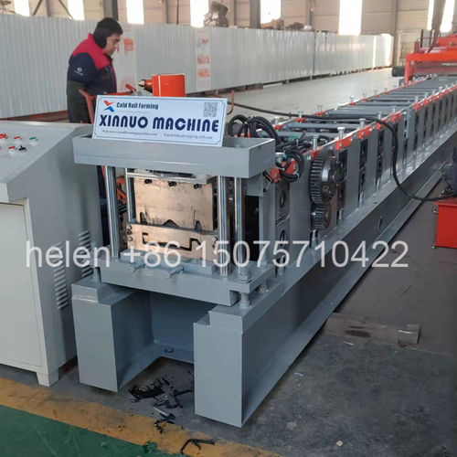
Coil loading on the decoiler, strip entry through the guide, progressive forming of the rib pattern across the roll train with the interlock profile developed at the edge forming provision, length measurement, hydraulic cutting, and discharge to the run-out position follow the established sequence, with the section and edge geometry set by roller tooling produced to the buyer's drawing.
Hebei Xinnuo is a professional cold roll forming machinery manufacturer with 20+ years of experience. We specialize in C/Z purlin machines, roof panel roll formers, floor deck machines, and custom profile solutions — exported to 50+ countries worldwide.