helen@hbxinnuorollforming.com
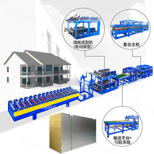
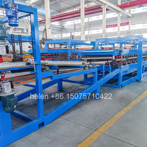
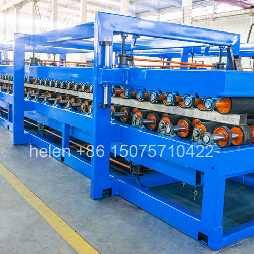
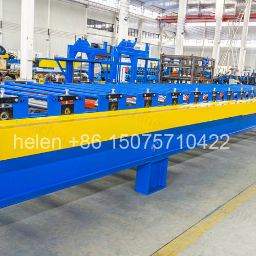
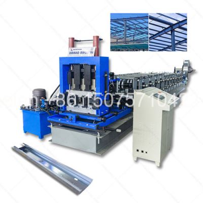
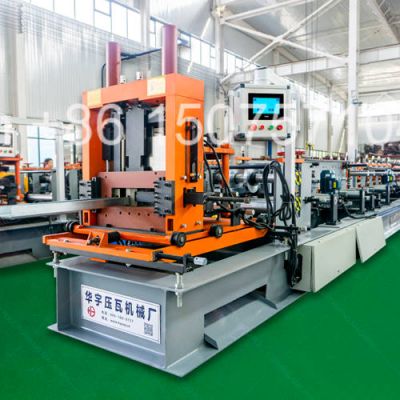
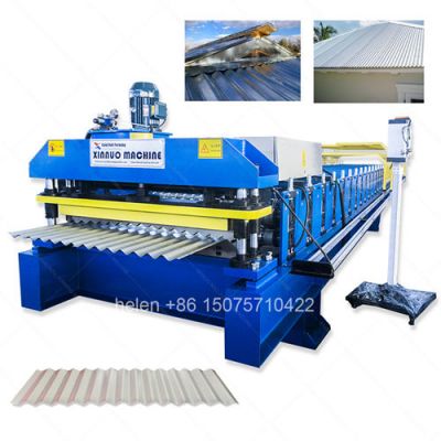
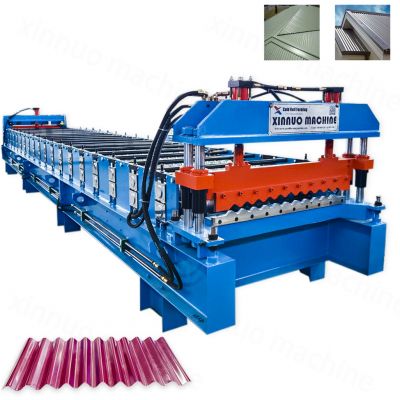
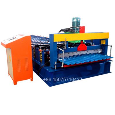
Z lock sandwich panel making machine for manufacturing EPS, rock wool, PU and glass wool insulated composite panels. Self-locking interlocking concealed fastener joint profile. Automatic PLC control with continuous roll forming and inline cutting system.
| Specification | Value |
|---|---|
| Finished Panel Width | 950 mm / 970 mm / 1000 mm / 1050 mm |
| Panel Core Thickness | 50 mm – 150 mm (200 mm optional) |
| Top Skin Material Gauge | 0.30 mm – 0.80 mm galvanized / color-coated steel |
| Bottom Skin Material Gauge | 0.30 mm – 0.60 mm galvanized / color-coated steel |
| Raw Coil Width Input | 1200 mm / 1250 mm |
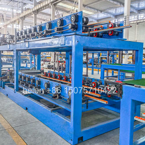
| Forming Roller Stations | 14 rows × 2 units (upper + lower, 28 total) |
| Roller Steel Grade | GCR15 (52100 equivalent), HRC 58–62 after heat treatment |
| Roller Machining Accuracy | CNC turned, ±0.05 mm concentricity |
| Main Frame Construction | 300H section welded steel, stress-relieved, 14 mm wall plates |
| Transmission Shafts | Φ70 mm diameter, induction hardened and tempered |
| Drive Configuration | 5 independent motor sets × 4 kW each, heavy-duty chain drive |
| Running Speed | 3 – 5 linear meters per minute (continuous) |
| Panel Length Range | 2,000 mm – 12,000 mm programmable |
| Length Accuracy | ±2 mm per panel |
| Main Power Requirement | 25 – 35 kW total, 380V ±10% / 50Hz / 3-phase |
| Machine Footprint (L×W×H) | Approx. 50,000 × 4,000 × 3,500 mm |
| Decoiler Capacity | 5 metric tons × 2 units, hydraulic expansion mandrel |
| Operator Interface | Color touchscreen PLC HMI, multi-language support |
| Performance Indicator | Z Lock Interlocking Joint | Standard Lap / Screw Joint |
|---|---|---|
| Installation Labor | Snap-lock engagement, 30–40% less site labor | Manual screw driving per linear meter |
| Weather Integrity | Continuous mechanical interlock with 3 seal lines | Single-point gasket compression around each screw |
| Visual Quality | Flush surface, no visible fasteners | Screw heads and washers visible on panel face |
| Thermal Efficiency | Unbroken insulation, zero thermal bridging at joints | Metal screws create cold bridges every 300–400 mm |
| Maintenance Cost | No fastener inspection or retightening required | Periodic screw check and seal replacement needed |
| Wind Uplift Resistance | Full-length mechanical engagement distributes load | Load concentrated at individual screw points |
| Insulation Type | Typical Density | K-Value (W/m·K) | Reaction to Fire | Primary Industry Use |
|---|---|---|---|---|
| EPS (Expanded Polystyrene) | 12 – 18 kg/m³ | 0.038 | Euroclass E / B2 | Standard warehouses, farm buildings, low-rise commercial |
| Rigid PU (Polyurethane) | 38 – 45 kg/m³ | 0.022 | Euroclass C–D / B1–B2 | Cold rooms, freezers, temperature-controlled logistics |
| Mineral Rock Wool | 80 – 120 kg/m³ | 0.040 | Euroclass A1 (non-combustible) | High-rise facades, fire compartments, public buildings |
| Glass Wool Fiber | 24 – 48 kg/m³ | 0.035 | Euroclass A1–A2 | Interior partitions, acoustic barriers, mechanical rooms |
| Market Sector | Typical Panel Use |
|---|---|
| Cold Chain & Logistics | Freezer compartment envelopes, chilled storage dividers, temperature-controlled loading bays |
| Heavy Industrial | Steel mill cladding, power plant turbine halls, cement factory enclosures |
| Commercial Real Estate | Shopping center external walls, office tower spandrel panels, hotel partition systems |
| Pharma & Electronics | ISO cleanroom wall and ceiling systems, static-controlled manufacturing suites |
| Agribusiness | Climate-controlled poultry and livestock housing, grain storage insulation, greenhouse side walls |
| Modular & Portable | Prefab container home exteriors, site office cabins, temporary classroom units |
| Food & Beverage | Hygienic processing room walls, bakery proofing chambers, brewery cold conditioning rooms |
| Phase | What Happens | Machine Section |
|---|---|---|
| 1. Material Feeding | Two steel coils — one for the top panel face, one for the bottom — are loaded onto independent powered decoilers. Pneumatic loop control maintains consistent strip tension as the coils unwind into the forming section | Dual hydraulic decoiler station (5-ton each) |
| 2. Profile Shaping | Each steel strip passes through a sequence of 14 progressively shaped roller pairs. The Z lock male rib is gradually formed on the top skin edge while the matching female channel is shaped on the bottom skin edge. Roller gaps are preset at the factory and do not require operator adjustment | Upper & lower 14-station roll forming banks |
| 3. Core Insertion | The insulation material is placed between the two formed metal skins. EPS sheets and rock wool batts are conveyor-fed; PU foam systems inject liquid reactants that expand and cure in place. Edge guides maintain the core centered within the panel width | Core material feed conveyor |
| 4. Bonding | Two-part polyurethane adhesive — supplied from separate reservoirs through independent metering pumps — is applied to both the top-skin-to-core and bottom-skin-to-core interfaces. Application width and thickness are digitally set to match panel dimensions | Dual-circuit glue application station |
| 5. Panel Consolidation | The assembled sandwich passes between upper and lower pressure belts inside a 9-meter heated curing tunnel. Uniform pressure across the full panel width ensures intimate contact between all three layers until the adhesive reaches handling strength | 9-meter heated lamination press |
| 6. Edge Cleanup | Excess core material and steel overhang are trimmed from both panel edges. The Z lock profiles on the left and right edges are checked against a go/no-go gauge to confirm interlocking fit | Edge trimming and profile verification station |
| 7. Panel Cutoff | The moving panel passes through the flying shear which accelerates to match line speed, clamps, and cuts in under one second. Cut length is read from an encoder wheel and cross-checked against the PLC setpoint | Hydraulic flying shear with encoder feedback |
| 8. Output & Packaging | Cut panels discharge onto the collection table. Operators inspect, stack to pre-defined bundle heights, apply edge protectors, and wrap with stretch film for warehouse storage or direct container loading | Run-out table and manual stacking area |
The machine operates as a single synchronized system under one PLC controller. An operator sets the target panel length, running speed, and glue flow rate on the touchscreen before starting production. Once running, the flying shear cuts panels to length automatically — no stopping, no manual measurement, no batch counting. Production data including total meters run, panels produced, and average speed are logged and can be exported for shift reporting.
Hebei Xinnuo is a professional cold roll forming machinery manufacturer with 20+ years of experience. We specialize in C/Z purlin machines, roof panel roll formers, floor deck machines, and custom profile solutions — exported to 50+ countries worldwide.